Bearing assembly with fluid circuit for delivery of lubricating fluid between bearing surfaces

Inactive Publication Date: 2005-03-03
GENERAL ELECTRIC CO
View PDF3 Cites 43 Cited by
  • Summary
  • Abstract
  • Description
  • Claims
  • Application Information

AI Technical Summary

Benefits of technology

[0009]FIG. 1 is a cutaway view of an exemplary turbocharger that may benefit from an improved fluid ci

Problems solved by technology

The high speeds and/or pressure ratios that, for example, may be required for state-of-the-art turbocharger applications could result in excessive metal temperatures of rotating components in a turbocharger, such as a thrust bearing.
One problem in bearing applications is the high heat that may be generated between rotating bearing surfaces at high loads.
This problem becomes even more challenging in cases where slight misalignments can lead to an uneven load distribution between a thrust collar and the thrust beari

Method used


Image

  • Bearing assembly with fluid circuit for delivery of lubricating fluid between bearing surfaces
  • Bearing assembly with fluid circuit for delivery of lubricating fluid between bearing surfaces
  • Bearing assembly with fluid circuit for delivery of lubricating fluid between bearing surfaces

Examples


Embodiment Construction

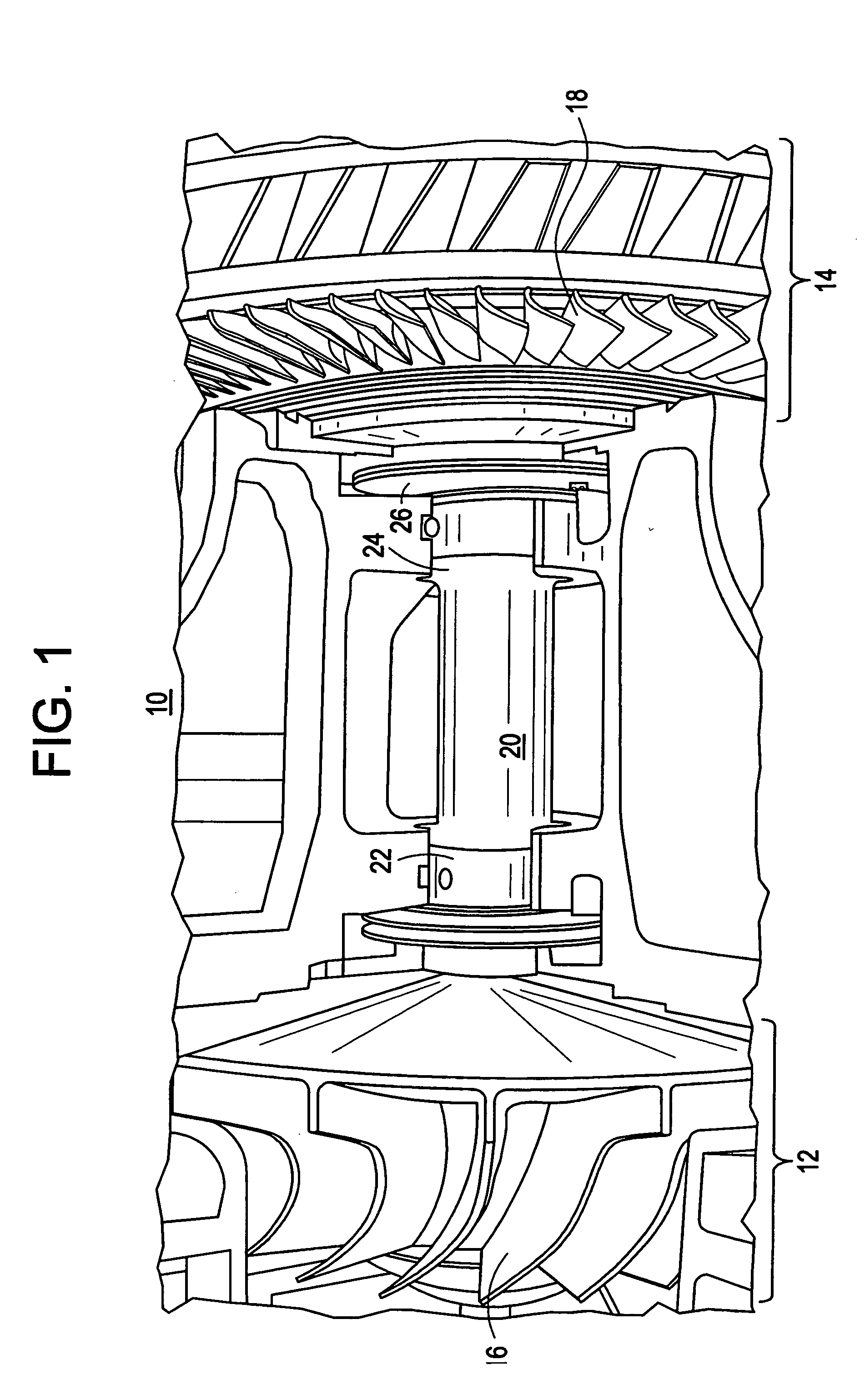
[0019]FIG. 1 shows a cutaway view of an exemplary turbocharger 10 that may benefit from the teachings of the present invention. Turbocharger 10 generally comprises respective compressor and turbine stages 12 and 14 including a compressor wheel 16 and a turbine wheel 18 coupled through a rotatable shaft 20. Shaft 20 may be supported by a bearing system that, in one exemplary embodiment, may include a journal bearing 22 at one end thereof (e.g., near compressor stage 12), and a bearing assembly at an opposite end of the shaft (e.g., near turbine stage 14). The bearing assembly may integrate a journal bearing 24 and a thrust bearing 26. The bearing system is configured to provide both radial support (through the journal bearings) and axial support (through the thrust bearing) to shaft 20 in a manner well understood by those skilled in the art.

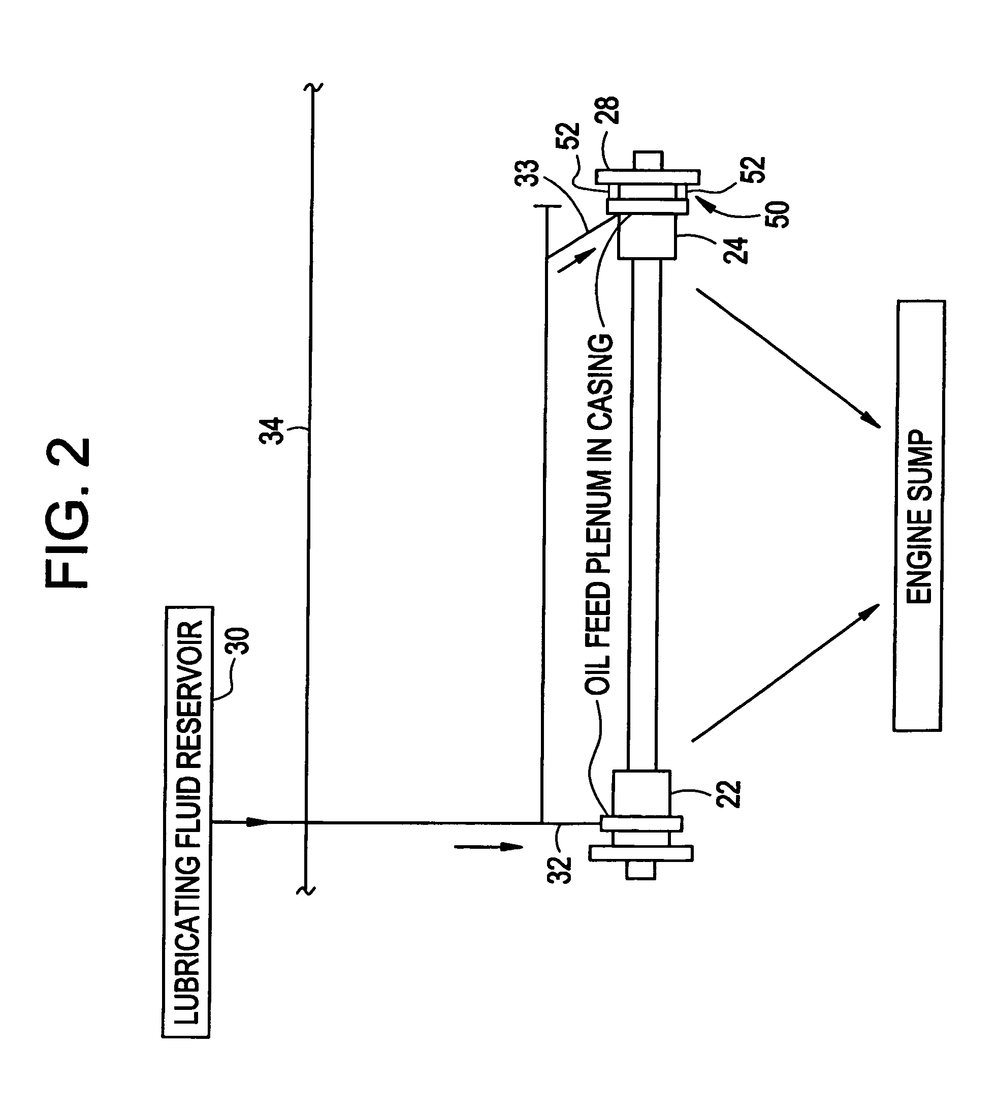
[0020] In operation, the shaft 20 may be supported in a film of lubricating fluid by the journal and thrust bearings. In one related design, imp...


PUM


Abstract

An integral thrust/journal bearing assembly, e.g., useable in a turbocharger is provided. The assembly includes a journal bearing configured to operate at a first mechanical load. The assembly further includes a thrust bearing including a thrust bearing face. The thrust bearing may be configured to operate at a second mechanical load different than the first mechanical load. A fluid circuit that includes parallel branches is provided within the integral bearing assembly for delivering parallel flows of lubricating fluid to the thrust bearing face and the journal bearing.

Description

FIELD OF THE INVENTION [0001] The present invention is generally related to bearings, and, more particularly, to a fluid circuit and techniques for delivery of lubricating fluid between bearing surfaces of an integral thrust / journal bearing assembly. BACKGROUND OF THE INVENTION [0002] The high speeds and / or pressure ratios that, for example, may be required for state-of-the-art turbocharger applications could result in excessive metal temperatures of rotating components in a turbocharger, such as a thrust bearing. For example, temperatures exceeding the material design limits have been measured on the thrust bearing at high turbo speeds. [0003] One problem in bearing applications is the high heat that may be generated between rotating bearing surfaces at high loads. This problem becomes even more challenging in cases where slight misalignments can lead to an uneven load distribution between a thrust collar and the thrust bearing surfaces. This may result in poor lubrication and cool...

Claims


Application Information

Patent Timeline
IPC IPC(8): F01D25/16F16C17/02F16C17/04F16C33/10F16N7/40
CPCF01D25/168F16C17/02F16C17/04F16C2360/24F16N7/40F16N2210/02F05D2220/40F16C33/1065
Inventor KERAMATI, BAHRAMFURMAN, ANTHONY HOLMESSWENSON, KENDALL ROGERLORINGER, DANIEL EDWARD
Owner GENERAL ELECTRIC CO
Why Eureka
Try Eureka