Control and system for dispensing fluid material

a technology of fluid material and control system, which is applied in the direction of liquid/solution decomposition chemical coating, superimposed coating process, manufacturing tools, etc., can solve the problems of operating abnormalities, wear of components of the dispensing system, etc., and achieves cost saving and quality seal. better

Inactive Publication Date: 2005-03-03
FANUC ROBOTICS NORTH AMERICA
View PDF14 Cites 37 Cited by
  • Summary
  • Abstract
  • Description
  • Claims
  • Application Information

AI Technical Summary

Benefits of technology

The method is characterized by at least a portion of the second time period occurring consecutively with the first time period to compensate for changes in operational characteristics of the viscous material and the dispensing system thereby maintaining the actual dispensing rate within the minimum deviation of the target dispensing rate.
The present invention provides several advantages over the prior art, including Tofte et al. For instance, by determining the second new value for the compensation factor consecutively with determining the first new value for the compensation factor, the dispensing system can more quickly compensate the actual dispensing rate in the second time period for the changes in operational characteristics of the viscous material and the dispensing system during the first time period. Such changes include changes in viscosity, air bubbles in the dispensing system, plugged nozzles, and the like. As previously discussed, these changes can have an immediate impact on the actual dispensing rate of the viscous material. For instance, a change in viscosity requires immediate compensation to ensure that the viscous material is being dispensed within the minimum deviation of the target dispensing rate. The dispensing system and method of controlling the dispensing system of the present invention accomplish this by continually determining a new value for the compensation factor, i.e., recalculating the compensation factor. As a result, the method of the present invention provides a better quality seal in the case of the viscous material being a sealant, and saves costs by reducing excessive dispensing.

Problems solved by technology

Changes in the viscosity of the viscous material being dispensed, wear of components of the dispensing system, and operating abnormalities such as air bubbles within the dispensing system are common in such dispensing systems.
This periodic compensation frequency does not account for the dynamic characteristics of the viscous materials during each job cycle and the operating abnormalities that maybe encountered during each job cycle.
Conversely, periodically spaced time periods are not sufficient to compensate for changes in viscosity of a viscous material during dispensing.

Method used


Image

  • Control and system for dispensing fluid material
  • Control and system for dispensing fluid material
  • Control and system for dispensing fluid material

Examples


Embodiment Construction

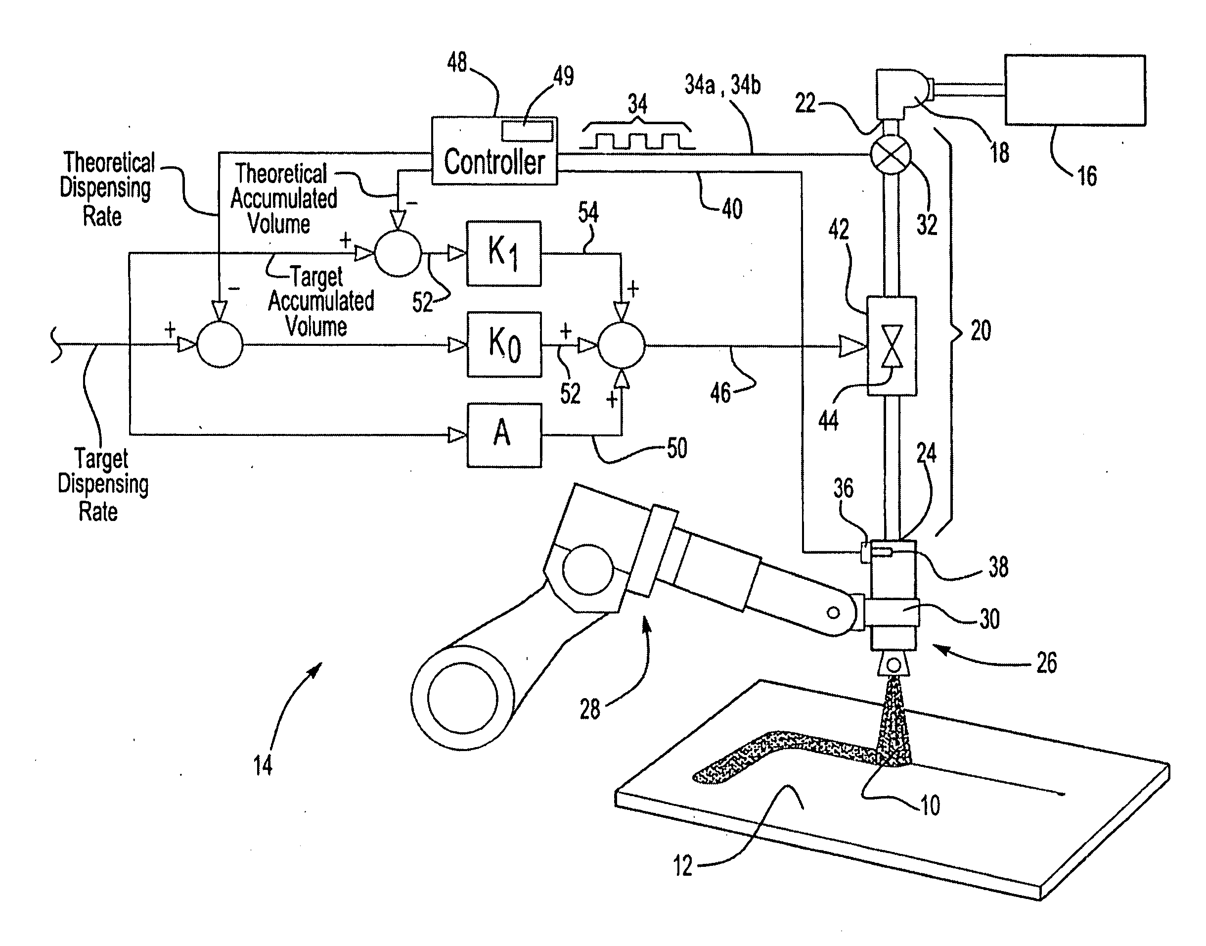
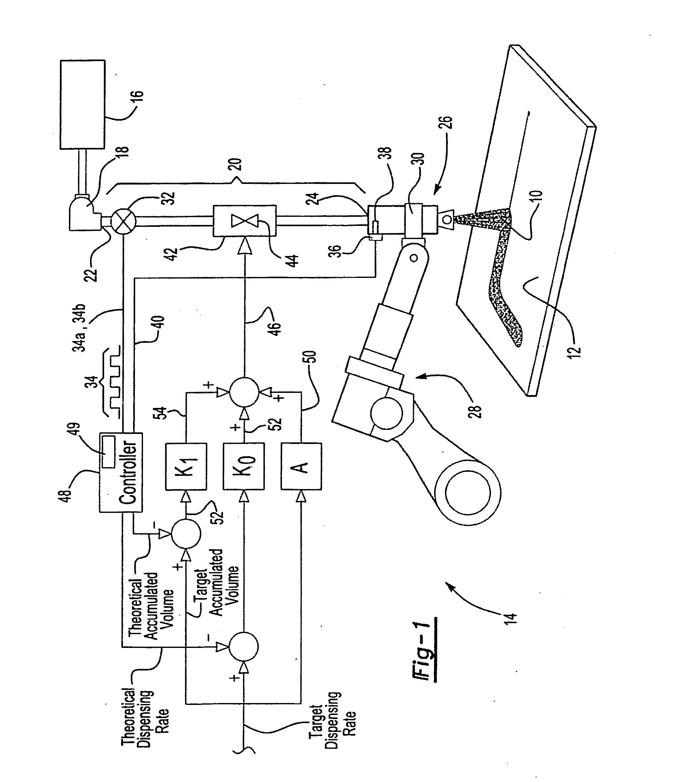
Referring to the Figures, wherein like numerals indicate like or corresponding parts throughout the several views, a dispensing system for dispensing a viscous material 10 onto a workpiece 12 at an actual dispensing rate that is within a minimum deviation of a target dispensing rate is generally shown at 14.

Dispensing System

The dispensing system 14 of the present invention is preferably used in industrial applications that require accurate dispensing of the viscous material 10 onto the workpiece 12. Such applications may include, but are not limited to, dispensing paint onto the workpiece 12, dispensing sealant onto the workpiece 12 to seal the workpiece 12 from moisture, or dispensing an adhesive onto the workpiece 12 to affix the workpiece 12 to a separate structure.

Referring to FIG. 1, a container 16 stores the viscous material 10 to be dispensed. A pump 18 receives the viscous material 10 from the container 16 and conveys the viscous material 10 through a delivery conduit...


PUM

PropertyMeasurementUnit
timeaaaaaaaaaa
viscosityaaaaaaaaaa
viscosityaaaaaaaaaa

Abstract

A method for controlling a fluid delivery system that includes a controllable pressure regulating device, a pressure sensor, a flow meter, and a controller. Initial values of a compensation factor and a cracking pressure are established, and a pressure of the fluid at each of a plurality of time increments occurring during periods while the fluid is dispensed is measured. A volume of the fluid dispensed during a first period, an average pressure at the time internals during the first period, and an actual average flow rate during the first period are determined. Then the average pressure value, the average flow rate value, a new compensation factor and a new cracking pressure are used to determine a theoretical flow rate for controlling the pressure regulating device and producing a pressure corresponding to the target flow rate.

Description

BACKGROUND OF THE INVENTION Dispensing systems are well known in industrial applications for dispensing viscous materials such as sealants, adhesives, coatings, and the like onto a workpiece. These applications may be to seal the workpiece, to adhere the workpiece to another structure, or to coat the workpiece. Changes in the viscosity of the viscous material being dispensed, wear of components of the dispensing system, and operating abnormalities such as air bubbles within the dispensing system are common in such dispensing systems. The changes in operational characteristics of the viscous material and the dispensing system continuously impact an actual dispensing rate of the viscous material. As a result, the prior art has attempted to provide methods to compensate the actual dispensing rate to account for such changes. Dispensing systems are well known in industrial applications for dispensing viscous materials such as sealants, adhesives, coatings, and the like onto a workpiec...

Claims


Application Information

Patent Timeline
Patent Type & Authority Applications(United States)
IPC IPC(8): B05B12/08B05C11/00B05C11/10B05D1/00
CPCB05C11/10B05B12/085B05C11/1013
Inventor YANAGITA, AKIHIROGUZOWSKI, RAYMONDLANKALAPALLI, KISHOREWIRTH, KARL F.BRUCE, DAVID
Owner FANUC ROBOTICS NORTH AMERICA
Why Eureka
Try Eureka