Multiband and multimode transmitter and method

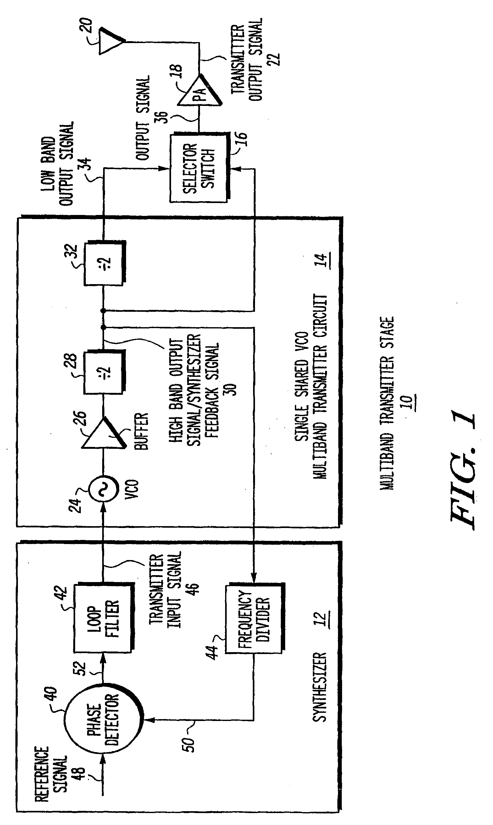
a multi-mode transmitter and multi-band technology, applied in the field of multi-mode transmitters, can solve the problems of unnecessarily high power consumption of the single shared vco multi-band transmitter circuit, noise performance and other performance criteria of the multi-band transmitter circuit, and the circuit b>14/b> configuration may not operate at optimal power consumption and noise performance levels

Active Publication Date: 2005-03-03
APPLE INC
View PDF24 Cites 24 Cited by
  • Summary
  • Abstract
  • Description
  • Claims
  • Application Information

AI Technical Summary

Problems solved by technology

However, using a single shared VCO 24 compromises power consumption, noise performance and other performance criteria for the multiband transmitter circuit 14.
As a result, the power consumption of the single shared VCO multiband transmitter circuit 14 when operating with the more stringent noise criteria for one band, such as in the 800 MHz or 900 MHz band, can result in unnecessarily high power consumption of the single shared VCO multiband transmitter circuit 14 when operating in a frequency band such as in the 1800 MHz or 1900 MHz band, where the noise criteria may be relatively less stringent.
Consequently, the single shared VCO 24 for the single shared VCO multiband transmitter circuit 14 configuration may not operate at optimal power consumption and noise performance levels.
Although this approach uses only a single shared VCO 24, adding the switching circuit and band-pass filters can add insertion loss, thus decreasing a level of the transmitter output signal 22 and increasing the generation of transmitter circuit noise.

Method used


Image

  • Multiband and multimode transmitter and method
  • Multiband and multimode transmitter and method
  • Multiband and multimode transmitter and method

Examples


Embodiment Construction

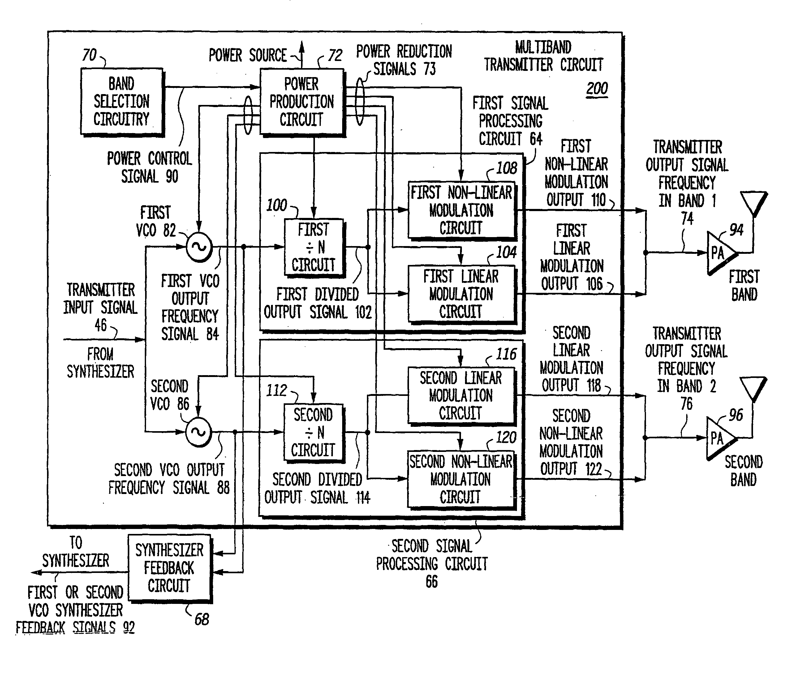
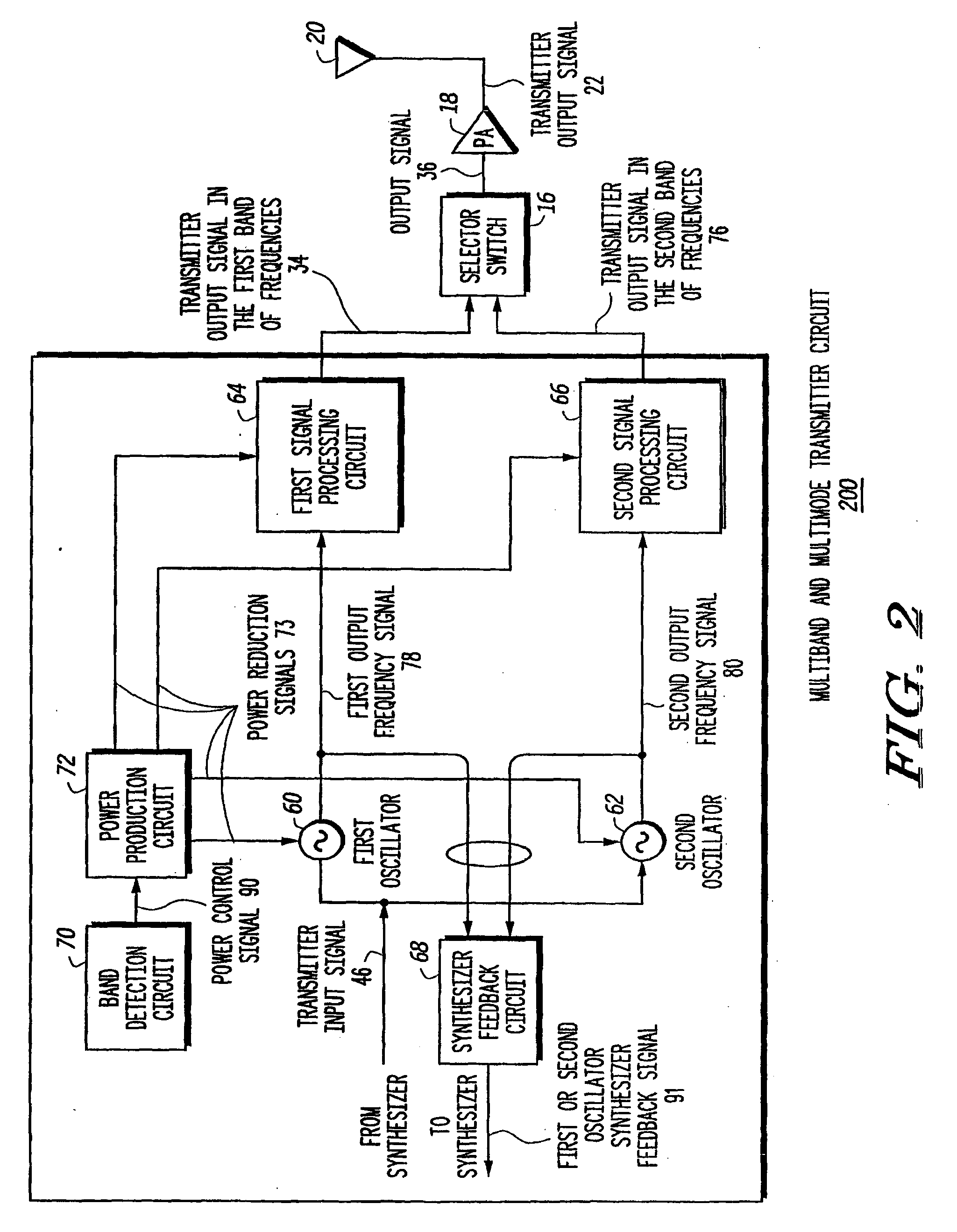
[0019] A multiband and multimode transmitter and method employs two separate oscillators, where one of the oscillators produces a transmitter output signal at one of multiple frequency bands. Each oscillator may be any suitable device that generates a periodic signal, such as an analog or digital signal. For example each oscillator may be a phase locked loop (PLL) circuit, a crystal oscillator circuit, or a voltage controlled oscillator (VCO) circuit. Since each oscillator functions to provide an output signal at a particular band of frequencies, each oscillator and a corresponding signal processing circuit may be optimized for the lowest power consumption while meeting the noise performance criteria in each of the multiple frequency bands.

[0020] The multiband and multimode transmitter circuit includes at least a first oscillator circuit and a first signal processing circuit to produce a first output frequency signal in a first band and at least a second oscillator circuit and a se...


PUM


Abstract

A multiband and multimode transmitter circuit (200) includes two separate oscillators, such as at least a first oscillator circuit (60), a second oscillator circuit (62), a corresponding first signal processing circuit (64), and second signal processing circuit (66) to produce a first output frequency signal (78) defined within the first or second band of frequencies in response to a transmitter input signal (46). Each oscillator and corresponding signal processing circuit (64, 66) may be optimized for the lowest power consumption while meeting the noise performance criteria in each of the multiple frequency bands. The multiband and multimode transmitter circuit (200) may produce the transmitter output signal (36) with either linear modulation or nonlinear modulation and at a first band or second band frequencies.

Description

FIELD OF THE INVENTION [0001] The invention relates generally to transmitters and, more particularly, to multiband transmitters. BACKGROUND OF THE INVENTION [0002] With the emergence of multiple radio frequency bands and multiple modulation modes available for wireless communications, there is a need for transmitting radio frequency (RF) communication signals within multiple frequency bands and multiple modulation modes. For example, the emergence of various communications standards has driven the need for wireless communication devices, such as wireless telephones, wireless personal data assistants (PDAs), pagers, two-way radios, and other types of wireless devices, to be compatible with multiple standards employing multiple modulation modes and multiple radio frequency bands. Having multimode and multiband capability allows a wireless device to operate with more than one system or standard, and, depending on the system available, the user can potentially use the device on more tha...

Claims


Application Information

Patent Timeline
Patent Type & Authority Applications(United States)
IPC IPC(8): H04B1/40
CPCH04B1/406
Inventor BALASUBRAMANIYAN, ARULPECKHAM, DAVID
Owner APPLE INC
Why Eureka
Try Eureka