Optical frequency comb signal generating device and method

A technology of signal generation and optical frequency comb, which is applied in the direction of laser devices, semiconductor laser devices, devices for controlling laser output parameters, etc., can solve the problems of integration of electroabsorption modulation lasers and semiconductor optical amplifiers, large carrier noise, The carrier phase relationship is not obvious, etc., to achieve the effect of simple structure, wide signal spectrum and large number of comb teeth

Inactive Publication Date: 2020-05-29
UNIV OF ELECTRONICS SCI & TECH OF CHINA
View PDF6 Cites 4 Cited by
  • Summary
  • Abstract
  • Description
  • Claims
  • Application Information

AI Technical Summary

Problems solved by technology

This method can generate an optical frequency comb with more comb teeth, but there are disadvantages such as the carrier phase relationship is not obvious and the carrier noise is large.
[0004] However, the integration of electro-absorption modulated lasers and semiconductor optical amplifiers is not mentioned in the above-mentioned several schemes.

Method used


Image

  • Optical frequency comb signal generating device and method
  • Optical frequency comb signal generating device and method
  • Optical frequency comb signal generating device and method

Examples


Embodiment 1

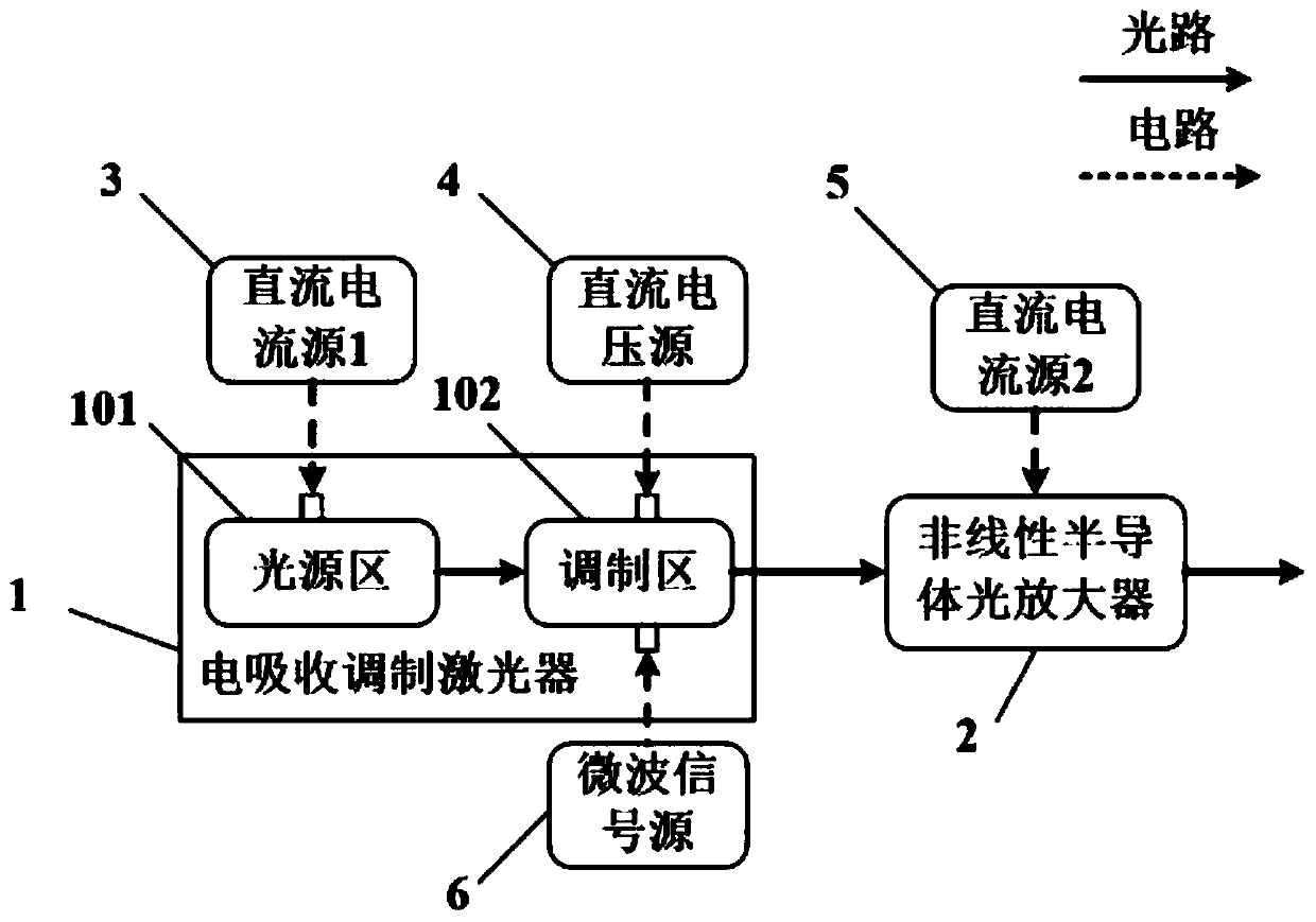
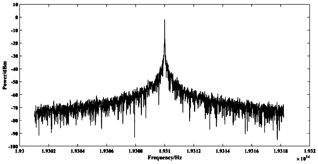
[0035] In this example, set the repetition frequency f of the optical frequency comb to be generated s Set the forward current output by the DC current source 1 to 35mA to make the light source area of ​​the electro-absorption modulated laser work normally, and the center frequency of the output optical signal f 0 It is 193.4THz, and then input to the modulation area of ​​the electro-absorption modulation laser, where the DC bias terminal and the RF input end of the electro-absorption modulation laser are not loaded with any voltage signal and microwave signal, and from the modulation area of ​​the electro-absorption modulation laser The output optical signal passes through the non-linear semiconductor optical amplifier, and its bias end has a forward current of 50 mA. At this time, the non-linear semiconductor optical amplifier works in the linear region and only amplifies the optical power, and then the output optical signal is observed by a spectrometer. Such as figure 2 Show...


PUM


Abstract

The invention discloses an optical frequency comb signal generating device and method. The light source area of an electro-absorption modulated laser is non-linearly modulated by the modulation area of the electro-absorption modulated laser, so that optical pulse signals are outputted; the repetition frequency of the optical pulse signals is equal to the frequency of a microwave signal source; thehigh-order sideband of integral multiples of the frequency of the microwave signal source is enhanced and expanded by a cascaded four-wave mixing effect of a non-linear semiconductor optical amplifier; and finally, an optical frequency comb is outputted. The optical frequency comb signal generating device is simple in structure and can be integrated; and optical frequency comb signals generated by the device are wide in frequency spectrum and have a large number of comb teeth.

Description

Technical field [0001] The invention belongs to the optical frequency comb generation technology in the field of optoelectronic technology, and specifically relates to an optical frequency comb signal generation device and a generation method. Background technique [0002] Optical frequency comb is a kind of optical signal with periodic optical pulses in the time domain and comb-shaped spectrum with equal frequency intervals in the frequency domain. It is widely used in precision measurement, optical communications, and microwave photonics. In addition, in the optical frequency comb patent applications of various countries and regions in the world, patents with US and Japanese companies as applicants account for the vast majority of optical frequency comb patents. Therefore, the value of optical frequency combs in the commercial field has been highlighted, and how to generate optical frequency combs with more comb teeth in a simple and integrable manner has become a research hots...

Claims


Application Information

Patent Timeline
Patent Type & Authority Applications(China)
IPC IPC(8): H01S5/042H01S5/06H01S5/0625H01S5/068H01S5/40H01S5/00
CPCH01S5/0085H01S5/0427H01S5/06H01S5/0615H01S5/06255H01S5/06821H01S5/4018
Inventor 张尚剑徐映王梦珂何禹彤刘永
Owner UNIV OF ELECTRONICS SCI & TECH OF CHINA
Why Eureka
Try Eureka