
Pulse ultra-wideband ranging system

A pulsed ultra-wideband, ranging system technology, applied in radio wave measurement systems, measurement devices, radio wave reflection/re-radiation and other directions, can solve the problems of complex receiving antenna structure, large receiver bandwidth, and high implementation costs. The effect of great practical value, wide spectrum and strong anti-interference ability

Inactive Publication Date: 2011-02-09
湖北三江航天红林探控有限公司
View PDF5 Cites 6 Cited by
  • Summary
  • Abstract
  • Description
  • Claims
  • Application Information

AI Technical Summary

Problems solved by technology

The main power of the transmitting signal frequency of the existing pulse ultra-wideband ranging system is concentrated below 1GHz. Due to the low frequency band of the signal, the structure of the transmitting antenna and the receiving antenna is complicated and the size is large, and the bandwidth of the receiver is relatively large. High-speed data is required. Analog-to-analog conversion circuit (digital-to-analog conversion rate greater than 500MHz), high implementation cost

Method used


Image

  • Pulse ultra-wideband ranging system
  • Pulse ultra-wideband ranging system
  • Pulse ultra-wideband ranging system

Examples


Embodiment Construction

[0022] The present invention will be described in further detail below in conjunction with the accompanying drawings.

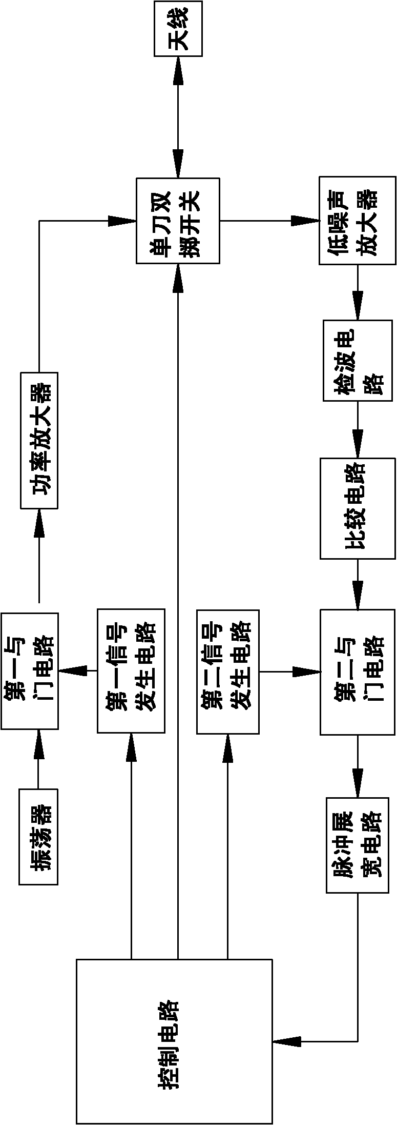
[0023] Such as figure 1 As shown, the present invention consists of a control circuit, an oscillator, a first signal generating circuit, a single pole double throw switch, a power amplifier, an antenna, a first AND gate circuit, a low noise amplifier, a detection circuit, a comparison circuit, a second signal generating circuit, The second AND gate circuit and pulse stretching circuit are composed.

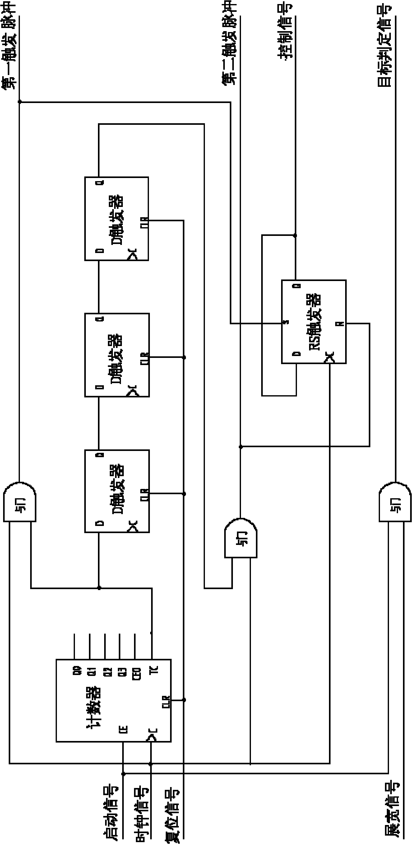
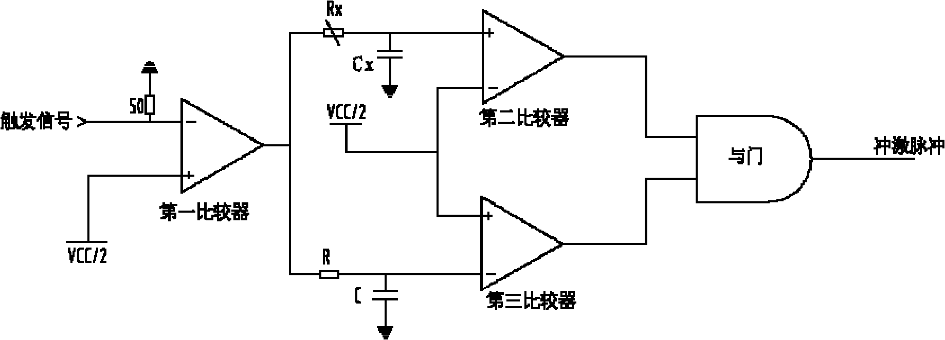
[0024] The control circuit is respectively connected to the first signal generating circuit, the second signal generating circuit and the SPDT switch control end; the first signal generating circuit and the oscillator are respectively connected to the two input ends of the first AND gate circuit; the output of the first AND gate circuit is connected to Power amplifier, the power amplifier is connected to the normally closed point of the SPDT switch; the center p...


PUM


Abstract

The invention relates to a pulse ultra-wideband ranging system, comprising a control circuit, a first signal generation circuit, a second signal generation circuit, an oscillator, a power amplifier, an antenna, a low noise amplifier, a detection circuit, a comparing circuit and a pulse stretching circuit. A controller controls the first signal generation circuit and the oscillator to generate an ultra wideband pulse signal which is amplified and transmitted through the antenna; after the ultra wideband pulse signal encounters a target, a refection signal is amplified through the low noise amplifier and an echo envelope signal is detected by the detection circuit, and the echo envelope signal generates an echo effective pulse after passing through the comparing circuit; the controller delays for a certain time and controls the second signal generation circuit and the echo effective pulse to generate a target effective pulse; and the target effective pulse is stretched to be a stretching signal by the pulse stretching circuit and the stretching signal is sent to the control circuit, and the control circuit judges whether the target is on the specified distance or not based on the condition whether the stretching signal exists or not. The invention simply solves the problems of generation, transmission and detection of the ultra wideband signal, and facilitates the mini-sized design.

Description

technical field [0001] The invention belongs to a radio ranging system, in particular to a pulse ultra-wideband ranging system for radio ranging. Background technique [0002] Modern high-tech has higher and higher requirements for ranging systems, especially for anti-jamming capabilities, detection accuracy, and non-cooperative target ranging. The traditional pulse radio ranging system cannot meet the needs of modern ranging because of its narrow instantaneous bandwidth, poor anti-interference ability, low detection accuracy, and large short-range blind zone. UWB technology is produced under this demand. [0003] It is generally considered that the fractional bandwidth of the signal , it is an ultra-wideband signal, where f H and f L are the highest and lowest frequencies of the signal band, respectively. It is difficult for a general signal to obtain a huge instantaneous bandwidth. For example, a chirp signal with a large time-width bandwidth product relies on the tim...

Claims


Application Information

Patent Timeline
Patent Type & Authority Applications(China)
IPC IPC(8): G01S13/08G01S7/28
Inventor 陈俊
Owner 湖北三江航天红林探控有限公司
Learn More