
Linear and non-linear dual mode transmitter

a dual-mode transmitter and transmitter technology, applied in the direction of transmission, gain control, substation equipment, etc., can solve the problems of power amplifiers that cannot amplify constant envelope signals, and inability to achieve continuous envelope signals

Inactive Publication Date: 2009-01-06
AVAGO TECH INT SALES PTE LTD
View PDF21 Cites 5 Cited by
  • Summary
  • Abstract
  • Description
  • Claims
  • Application Information

AI Technical Summary

Benefits of technology

[0008]In another aspect, there is provided a method for adjusting the operation of a power amplifier in response to a change in modulation scheme implemented by a dual mode modulator. A dual mode modulator receives a data signal from an information source. A modulation mode of the dual mode transmitter is determined. The data signal is modulated according to the determined mode of modulation to produce a modulated signal. An amplifier is biased according to the mode of modulation and amplifies the modulated signal to produce an amplified modulated signal. The amplifier is biased as a linear amplifier during a linear modulation mode and is biased as a non-linear amplifier during a non-linear modulation mode. A power of the modulated signal is increased during the non-linear modulation mode so that an operating point of the amplifier remains substantially constant during linear and non-linear modulation modes. A feed-forward connection between the dual mode modulator and the amplifier provides an indication to the amplifier of a change in modulation mode. The feed-forward connection adjusts the biasing of the amplifier.

Problems solved by technology

Therefore, using a linear power amplifier to amplify a constant envelope signal decreases efficiency since unneeded power is consumed.
Alternatively, using a non-linear power amplifier to amplify a variable envelope signal causes intolerable distortion.
Further, using multiple power amplifiers to accommodate different modes of modulation wastes space and increases operating costs and integration costs when the dual mode transmitter is implemented on a single semiconductor chip.

Method used


Image

  • Linear and non-linear dual mode transmitter
  • Linear and non-linear dual mode transmitter
  • Linear and non-linear dual mode transmitter

Examples


Embodiment Construction

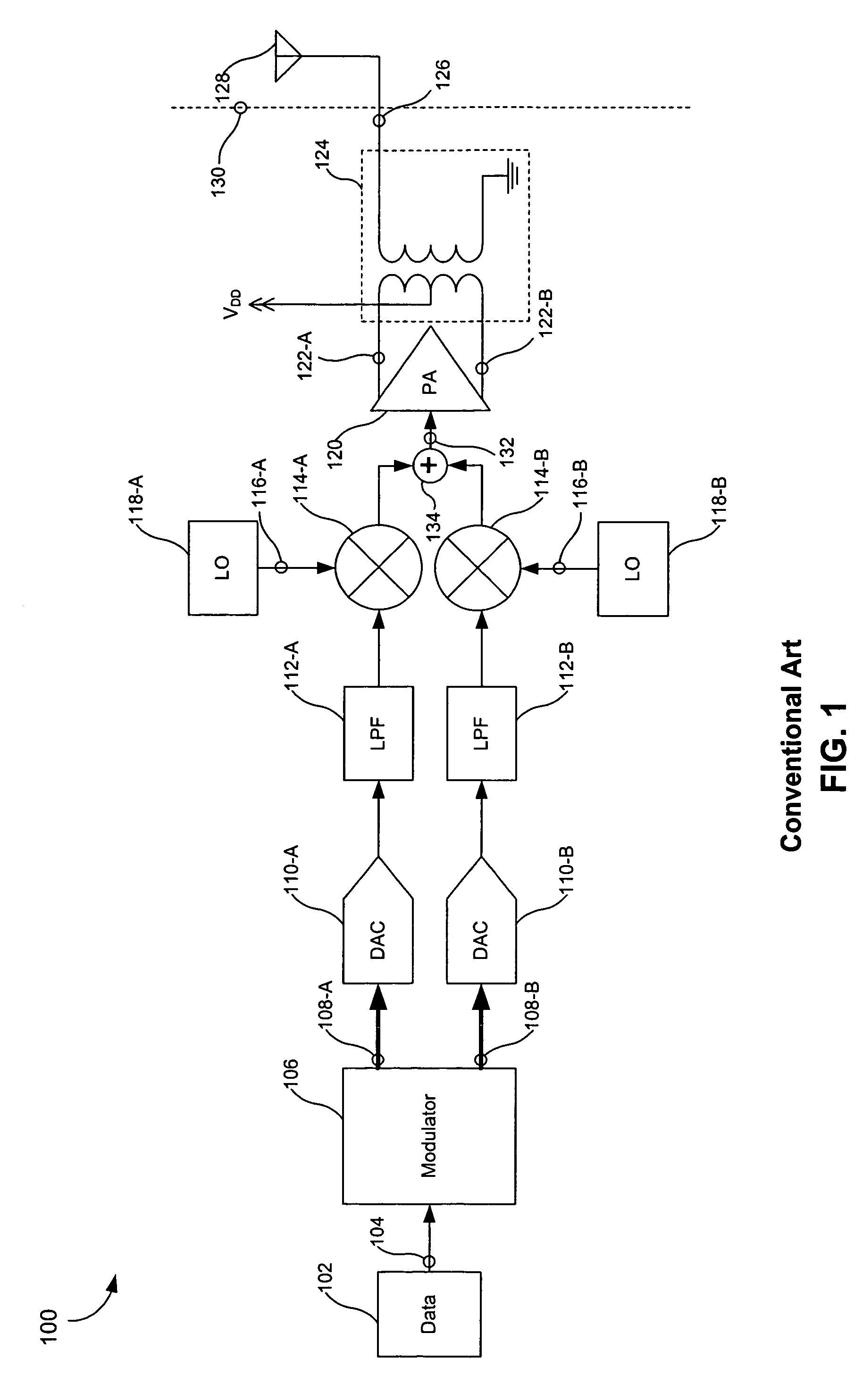
[0023]FIG. 1 illustrates a conventional wireless transmitter 100. The conventional wireless transmitter 100 includes an information source 102. The information source 102 generates a data signal 104. The data signal 104 is a sequence of bits. The information source 102 provides the data signal 104 to a conventional modulator 106. The conventional modulator 106 encodes and modulates the data signal 104 and provides two modulation channels (e.g., an in-phase channel and a quadrature-phase channel). Specifically, the conventional modulator 106 generates a modulated data signal 108-A and an associated modulated data signal 108-B. The modulated data signals 108-A and 108-B can be baseband signals or can be signals centered at an intermediate frequency (IF). The modulated data signals 108-A and 108-B are multiple-bit digital signals.

[0024]As illustrated in FIG. 1, the modulated data signals 108-A and 108-B are provided to digital-to-analog converters (DACs) 110-A and 110-B and to low-pass...


PUM


Abstract

A transmitter includes a dual mode modulator and an amplifier coupled to the dual mode modulator. The dual mode modulator implements a linear modulation scheme during a first mode of the modulator to produce a variable envelope modulated signal. The dual mode modulator implements a non-linear modulation scheme during a second mode of the modulator to produce a constant envelope modulated signal. The amplifier is biased as a linear amplifier during the first mode of the modulator and is biased as a non-linear amplifier during the second mode of the modulator. A feed-forward connection between the dual mode modulator and the amplifier is used to indicate a change in modulation mode and to adjust the bias of the amplifier. A power of the constant envelope modulated signal is increased such that an operating point of the amplifier remains substantially constant during the first and second modes of the modulator.

Description

BACKGROUND OF THE INVENTION[0001]1. Field of the Invention[0002]The present invention generally relates to dual mode transmitters. More specifically, the present invention provides a dual mode transmitter having an adjustable power amplifier to provide both linear and non-linear amplification.[0003]2. Background Art[0004]A dual mode transmitter is capable of implementing linear modulation schemes and non-linear modulation schemes and transmitting signals generated therefrom. A linear modulation scheme typically produces a variable envelope signal. A non-linear modulation scheme typically produces a constant envelope signal. A variable envelope signal requires linear amplification to prevent distortion of information encoded in the amplitude of the variable envelope signal. A constant envelope signal does not require linear amplification since the amplitude of a constant envelope signal does not contain information. Constant envelope signals can therefore tolerate distortion from non...

Claims


Application Information

Patent Timeline
Patent Type & Authority Patents(United States)
IPC IPC(8): H01Q11/12H04B1/02
CPCH03F1/0261H03F3/45188H03G3/3042H04B1/0003H04B1/0475H03G2201/103H03G2201/202H03G2201/307H03G2201/40
Inventor PAN, MENG-AN
Owner AVAGO TECH INT SALES PTE LTD
Learn More