Backup power device for elevator

a technology for backup power devices and elevators, applied in the direction of elevators, emergency power supply arrangements, circuit arrangements, etc., can solve the problem that the car still may fall freely

Inactive Publication Date: 2005-03-10
WANG JIUN JYH
View PDF6 Cites 13 Cited by
  • Summary
  • Abstract
  • Description
  • Claims
  • Application Information

AI Technical Summary

Benefits of technology

[0005] It is an object of the present invention to provide a backup power device for an elevator, comprising a brake including an upper brake controller and a manual brake rod; a damping assembly including a lever spaced apart from a top peripheral portion and coupled to the manual brake rod, the lever having a fulcrum, a roller at one end of the lever, and a wheel having a plurality of alternate recesses and risers equally spaced apart around its periphery; a motor including a shaft extended outwardly through the brake and the sheave to rotatably couple to the wheel, the shaft being controlled by the brake controller; a sheave having a traveling cable run through, the sheave and the traveling cable being operative to rotate as the shaft rotates; an electro-magnetic controller having a control rod; a pulley having a rope run through the manual brake rod and the control rod to extend downward; an electro-magnetic brake actuator on top of the brake controller; and a backup power supply; wherein the brake controller will activate automatically to brake the shaft in case of the failure of the elevator, the backup power supply will be enabled to supply power to the electro-magnetic brake actuator for activation, the brake controller, as driven by the electro-magnetic brake actuator, will operate intermittently to cause the brake to brake and release the shaft again in intervals, and the shaft will rotate slowly to hoist or lo...

Problems solved by technology

Unfortunately, the car still may fall freely if the car saf...

Method used


Image

  • Backup power device for elevator
  • Backup power device for elevator
  • Backup power device for elevator

Examples


Embodiment Construction

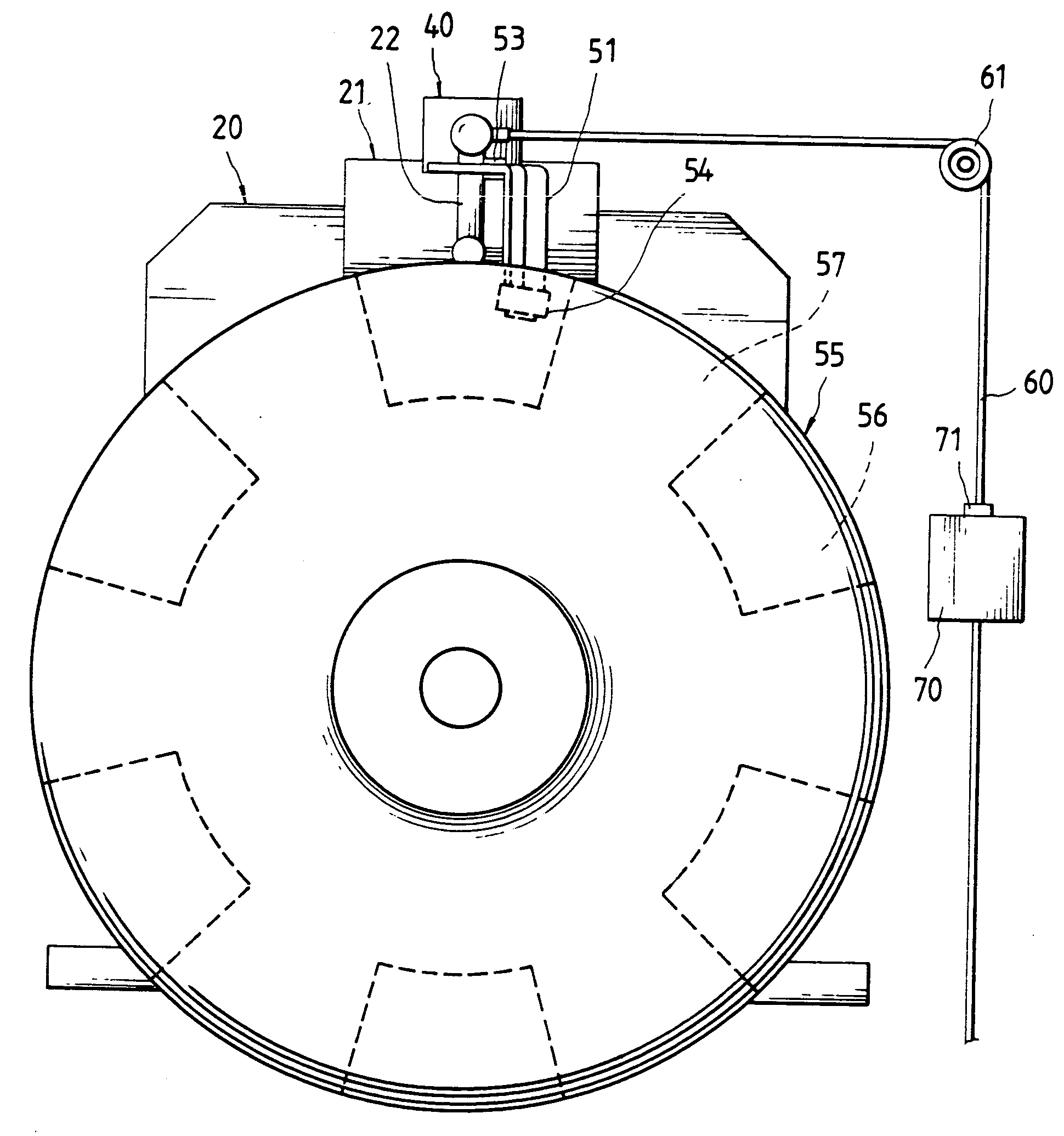
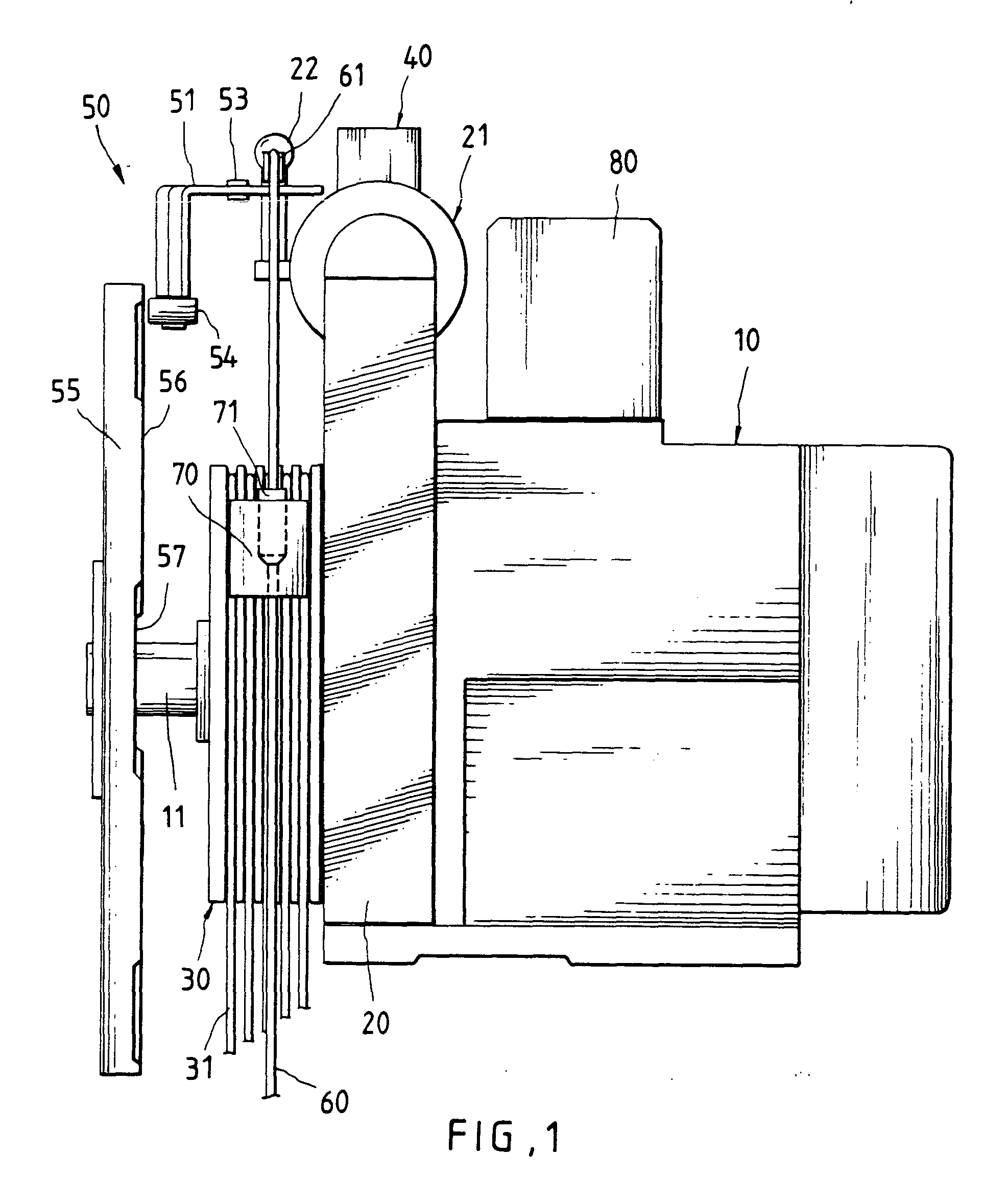
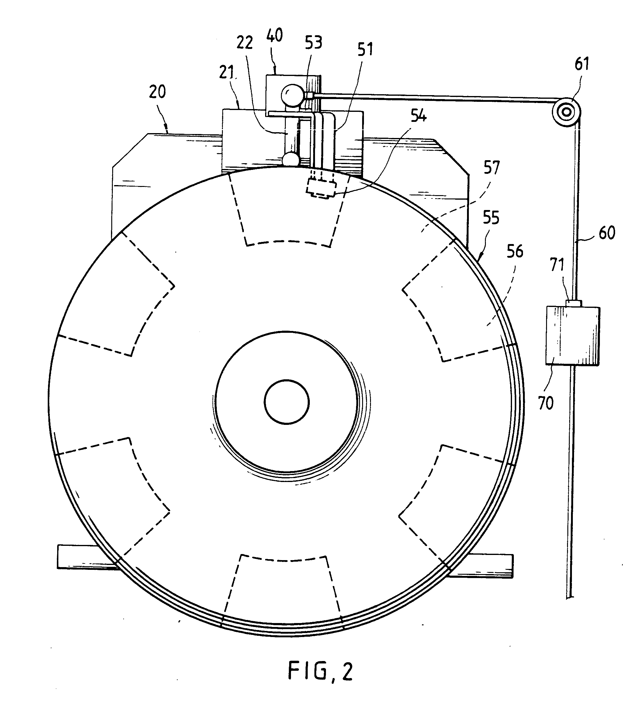
[0014] Referring to FIGS. 1, 2 and 3, there is shown a power device of elevator incorporating a backup power device constructed in accordance with the invention. The backup power device comprises a brake 20 including an upper brake controller 21, a sheave 30, a damping assembly 50, and a motor 10 including a shaft 11 extended outwardly through the brake 20 and the sheave 30 to rotatably couple to the damping assembly 50. The shaft 11 is controlled by the brake controller 21. Both the sheave 30 and a traveling cable 31 thereof rotate as the shaft 11 rotates. As an end, the elevator hoists or lowers.

[0015] The backup power device further comprises an electro-magnetic brake actuator 40 on top of the brake controller 21. The damping assembly 50 comprises a lever 51 spaced apart from a top peripheral portion and coupled to a manual brake rod 22 of the brake 20, the lever 51 having a central fulcrum 53, a roller 54 at a lower end of the lever 51, and a wheel 55 having a plurality of alte...


PUM


Abstract

Backup power device for an elevator comprises a brake including a brake controller and a manual brake rod, a damping assembly including a roller at one end of a lever, and a wheel having alternate recesses and risers, an electro-magnetic controller having a control rod, a pulley having a rope run through the manual brake rod and the control rod, an electro-magnetic brake actuator, and a backup power supply. A passenger trapped in the car can pull down the rope in case of the failure of the electro-magnetic controller, the electro-magnetic brake actuator, and the backup power supply as the lever turns to cause the roller to contact the recess or the riser. The lever moves intermittently to cause the manual brake rod to activate the brake controller for braking and releasing a motor shaft again in intervals. Eventually, the passenger can escape.

Description

BACKGROUND OF THE INVENTION [0001] 1. Field of the Invention [0002] The present invention relates to safety device of elevator and more particularly to a backup power device being automatically or manually operable in case of the failure of the elevator. [0003] 2. Description of Related Art [0004] Conventionally, the speed of an elevator motor is regulated by a frequency changer circuit. Also, a car safety device is required to install in the elevator as a backup power device in case of the failure of the elevator (e.g., particularly one having a motor regulated by a frequency changer circuit). Unfortunately, the car still may fall freely if the car safety device also breakdowns in case of the failure of the elevator. Hence, a need for improvement exists. SUMMARY OF THE INVENTION [0005] It is an object of the present invention to provide a backup power device for an elevator, comprising a brake including an upper brake controller and a manual brake rod; a damping assembly including ...

Claims


Application Information

Patent Timeline
IPC IPC(8): B66B5/02
CPCB66B5/027
Inventor WANG, JIUN JYH
Owner WANG JIUN JYH
Why Eureka
Try Eureka