Piezoelectric power generation system and sensor system

a power generation system and sensor technology, applied in piezoelectric/electrostrictive/magnetostrictive devices, pulse techniques, electronic switching, etc., can solve the problems of inability to achieve efficient power generation and power generation technique, and achieve the effect of reducing the dependence on the direction of externally driven vibration during power generation, reducing the labor intensity of installation and adjustment, and reducing the dependence on externally driven vibration

Inactive Publication Date: 2005-03-10
HITACHI LTD
View PDF3 Cites 27 Cited by
  • Summary
  • Abstract
  • Description
  • Claims
  • Application Information

AI Technical Summary

Benefits of technology

[0014] The effect of the present invention can be summarized as follows:
[0015] (1) using a vibrator having a large degree of freedom, the dependency on the direction of externally driven vibration during power generation can be minimized, allowing the labor for the installation and adjustment to be alleviated or eliminated, resulting in an improvement of installation of the piezoelectric power generation system.
[0016] (2) minimizing the dependency on the direction of the externally driven vibration permits flexible power generation with respect to the externally driven vibration, allowing an improvement in the efficiency of power generation in the piezoelectric power generation system.
[0017] (3) the layout of the sensor system with the piezoelectric power generation system placed at a furthest position from the subject on which the piezoelectric power generation system is to be mounted may improve the efficiency of the power supply in the sensor system.
[0018] (4) the sensor system is secured by a thread to the subject so that the installation of the sensor system is facilitated while keeping the high efficiency of power generation.

Problems solved by technology

The author of the present application has found that a problem resides in the power generation technique using the piezoelectric element as have been described above.
More specifically, in a power generation system that uses a plate-like piezoelectric element, while the power is generated by deforming the plate-like piezoelectric element through mechanical vibrational energy, externally driven vibration needs to be aligned with the deforming direction of the piezoelectric element, and efficient power generation cannot be achieved when the externally driven vibration is misaligned with the deforming direction of the piezoelectric element at the time of installation, or when the direction of the externally driven vibration occasionally changes.

Method used


Image

  • Piezoelectric power generation system and sensor system
  • Piezoelectric power generation system and sensor system
  • Piezoelectric power generation system and sensor system

Examples


first embodiment

[0043] First Embodiment

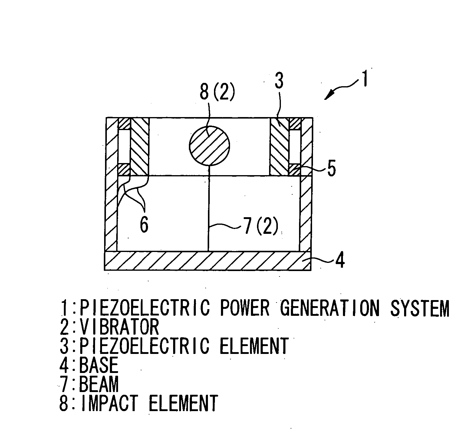
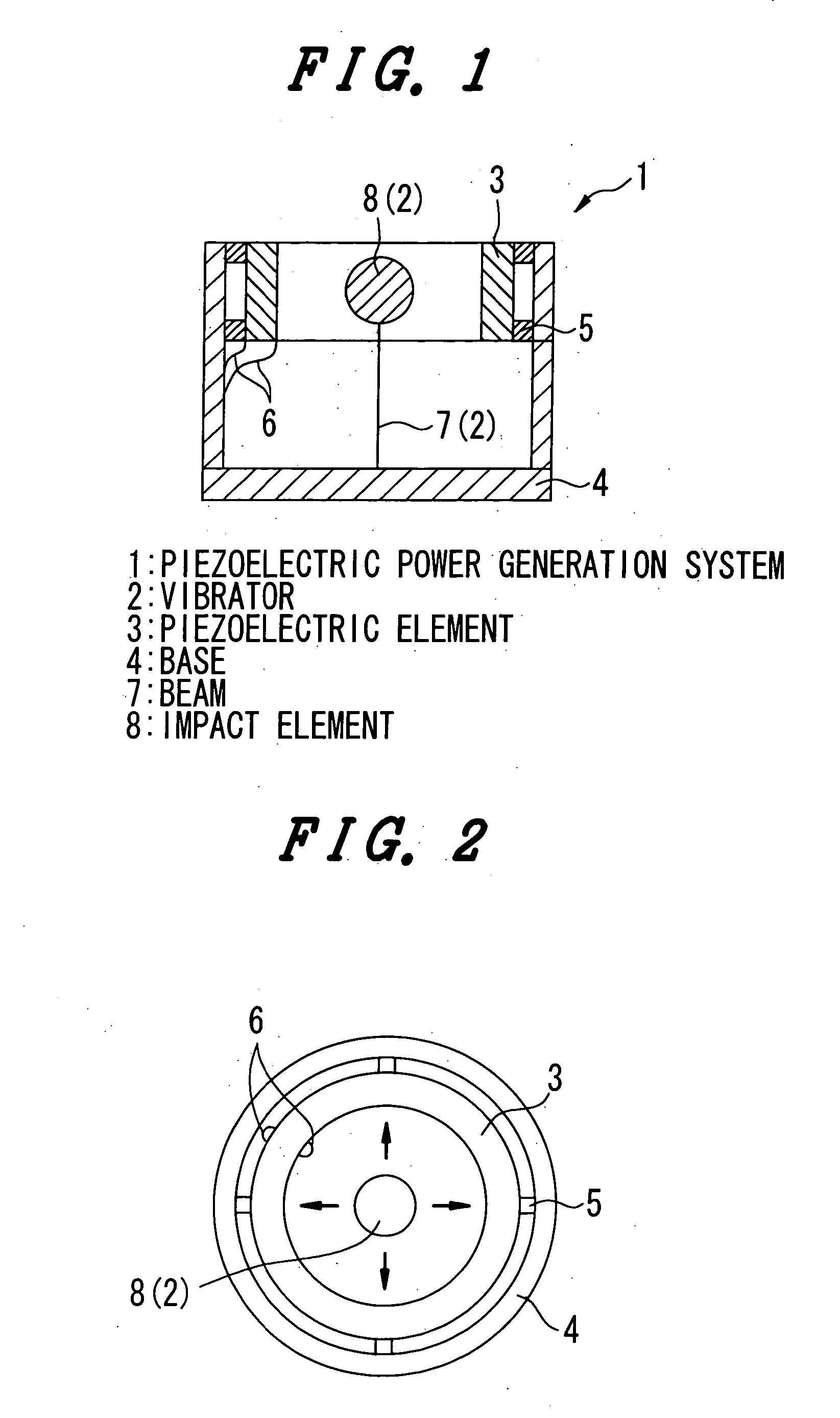
[0044]FIG. 1 shows a cross-sectional view of a piezoelectric power generation system of first preferred embodiment in accordance with the present invention, FIG. 2 shows a top plan view of a piezoelectric power generation system of FIG. 1, FIG. 3 shows a top plan view of another arrangement of the first preferred embodiment of the piezoelectric power generation system shown in FIG. 1

[0045] In the first preferred embodiment, the piezoelectric power generation system 1 converts mechanical vibrational energy into electrical energy. The piezoelectric power generation system 1 includes, as shown in FIG. 1, a vibrator 2, a piezoelectric element 3, a base 4, a spacer 5, and a wire 6.

[0046] The vibrator 2 comprises a beam 7, and an impact element 8. The beam 7 is in the form of a columnar or a cylindrical rod, at one end of which is fixed an impact element 8. The impact element 8 may be a steel ball or the like.

[0047] The piezoelectric element 3 is in the form of, f...

second embodiment

[0063] Second Embodiment

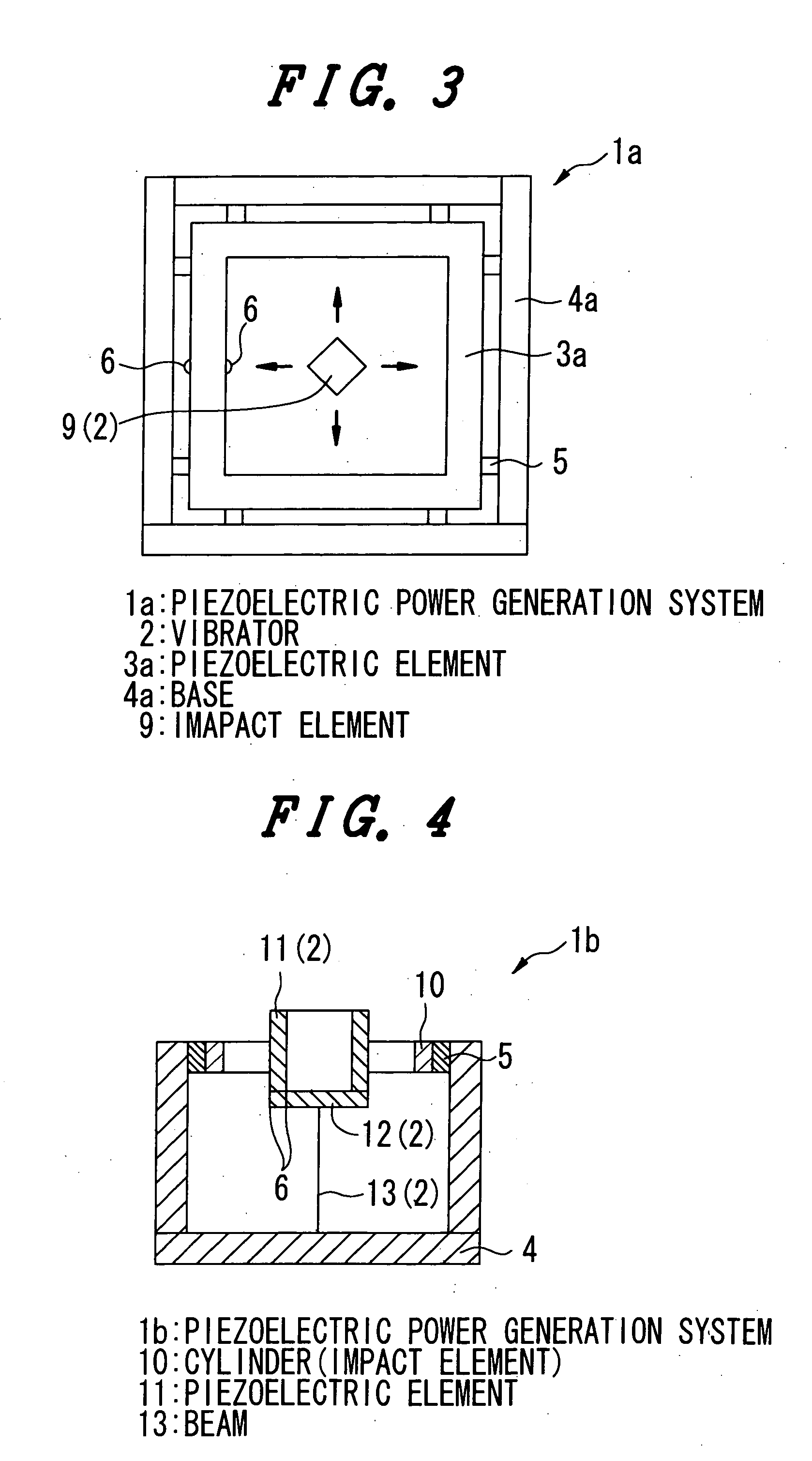
[0064]FIG. 4 shows a cross-sectional view of a piezoelectric power generation system of a second preferred embodiment in accordance with the present invention, FIG. 5 shows a top plan view of the piezoelectric power generation system shown in FIG. 4, FIG. 6 is a top plan view of another arrangement of the second preferred embodiment of the piezoelectric power generation system shown in FIG. 4.

[0065] In the second preferred embodiment of the present invention, the piezoelectric power generation system 1b includes a vibrator 2, a base 4, a spacer 5, a wire 6, and a cylinder (impact wall) 10, as shown in FIG. 4.

[0066] In this embodiment, the vibrator 2 comprises a piezoelectric element 11, a lid 12, and a beam 13. The piezoelectric element 11 is in the form of a cylinder and the bottom of one end of the cylinder of the piezoelectric element 11 has the hard lid 12. The wire 6 is connected to the piezoelectric element 11 for carrying electrical energy generated ...

third embodiment

[0083] Third Embodiment

[0084]FIG. 7 shows a cross-sectional view of a piezoelectric power generation system of a third preferred embodiment in accordance with the present invention, FIG. 8 shows a cross-sectional view of the piezoelectric power generation system shown in FIG. 7 along the line A-A′ of FIG. 7, and FIG. 9 is a cross-sectional view of another arrangement of the piezoelectric power generation system shown in FIG. 7.

[0085] In the third preferred embodiment of the present invention, the piezoelectric power generation system 1d of the third preferred embodiment includes, as shown in FIGS. 7 and 8, a piezoelectric element 15, lids (end plates) 16 and 17, a steel ball (impact element) 18, a beam 19, and a base 20. The base 20 is in the form of a plate, on the center of which one end of the beam 19 is fixed, which beam is in the form of a cylinder or columnar rod.

[0086] The piezoelectric element 15 is in the form of a cylinder and the lids 16 and 17 are provided at each end ...


PUM


Abstract

A piezoelectric power generation system which performs a highly efficient power generation using a piezoelectric element without dependency on the direction of an externally driven vibration. The piezoelectric power generation system includes a vibrator having a beam in the form of a rod, and an impact element such as a steel ball. At one end of the beam is fixed the impact element, and at the other end of the beam, the beam is fixed to the base. The outer circumference of the impact element carries the cylinder shaped piezoelectric element. When the base vibrates due to an externally driven vibration, the vibrator vibrates in synchronization with the given vibration in the radial direction of the base to cause the impact element of the base to impact with the inner surface of the cylindrical piezoelectric element, forcing the piezoelectric element to deform and thereby generate electrical power. The dependency on the vibration direction in the vibrator is minimized to significantly improve the efficiency of power generation.

Description

CLAIM OF PRIORITY [0001] The present application claims priority from Japanese Application JP 2003-313683 filed on Sep. 5, 2003, the content of which is hereby incorporated by reference into this application. FIELD OF THE INVENTION [0002] The present invention relates to a power generation technique for converting mechanical vibrational energy into electrical energy, and more particularly to an efficient applied power generation technique that uses vibrational energy to impact and strain a piezoelectric element. BACKGROUND OF THE INVENTION [0003] For example, in a power generation system that uses a piezoelectric element, the power is generated by arranging a terminal of a plate-like piezoelectric element to vibrate through an external stress and to resonate a free terminal to deform the piezoelectric element, or by impacting the plate-like piezoelectric element with a steel material to cause some deformation of the piezoelectric element. [0004] The author of the present application...

Claims


Application Information

Patent Timeline
Patent Type & Authority Applications(United States)
IPC IPC(8): H02N2/00H01L41/113H03K17/965
CPCH02N2/183
Inventor TANAKA, HIDETOSHIOHKUBO, NORIO
Owner HITACHI LTD
Why Eureka
Try Eureka