Plasma display panel

a technology of display panel and plasma, which is applied in the direction of address electrodes, electrical discharge tubes, electrical apparatus, etc., can solve the problems of unstable driving margin of outermost discharge cells, and achieve the stability of address discharge, and uniform driving voltage margin.

Inactive Publication Date: 2005-03-10
SAMSUNG SDI CO LTD
View PDF19 Cites 24 Cited by
  • Summary
  • Abstract
  • Description
  • Claims
  • Application Information

AI Technical Summary

Benefits of technology

[0021] As described above, the plasma display panel according to the present invention has the expanded portions formed in the regions of the address electrodes that correspond to the outermost discharge cells so that a greater amount of wall charge is generated within the discharge cells which improves the stability in the address discharge to the dis

Problems solved by technology

Sometimes the amount of movement is enough to cause a mis-discharge, but this is very unusual.
However, the outermost discharge cells placed adjacent to the edges of the PDP have a disadvantage for driving since the amount of priming particles to be accepted

Method used


Image

  • Plasma display panel
  • Plasma display panel
  • Plasma display panel

Examples


Embodiment Construction

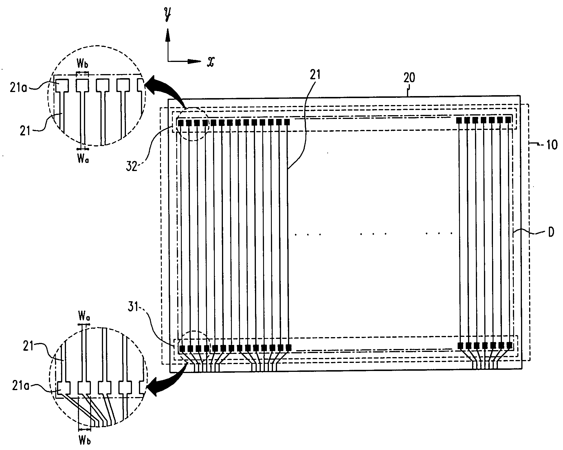
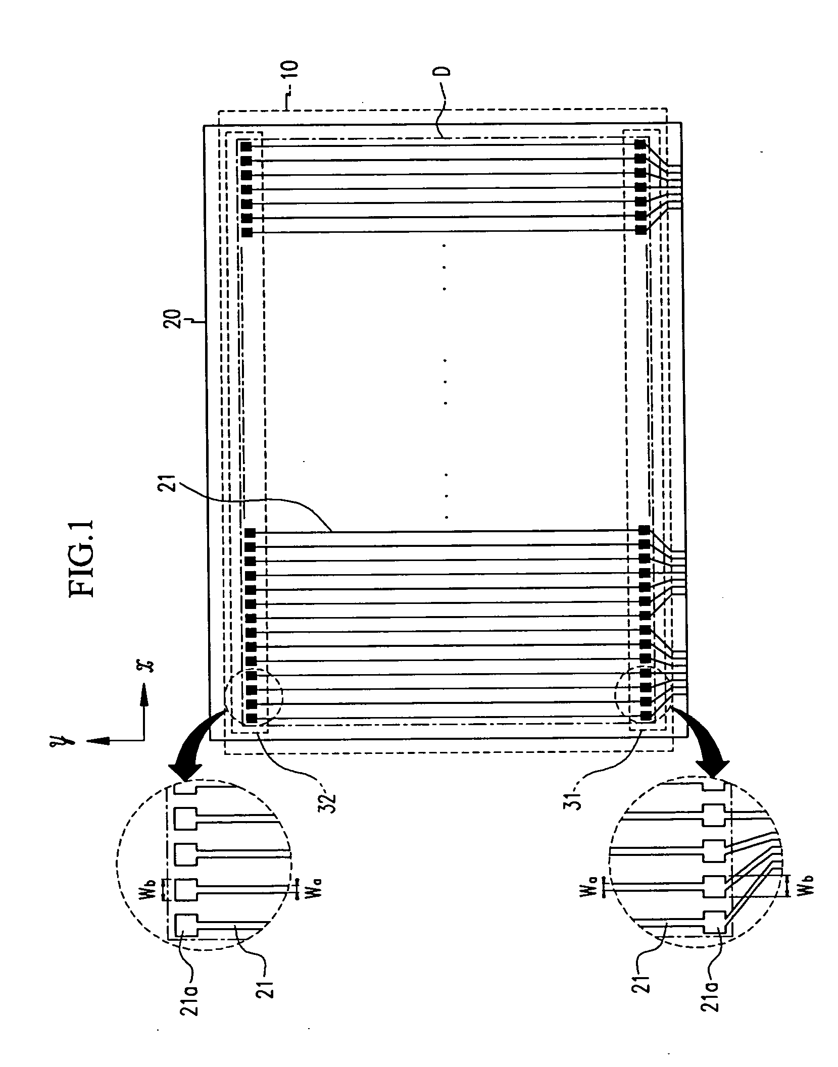
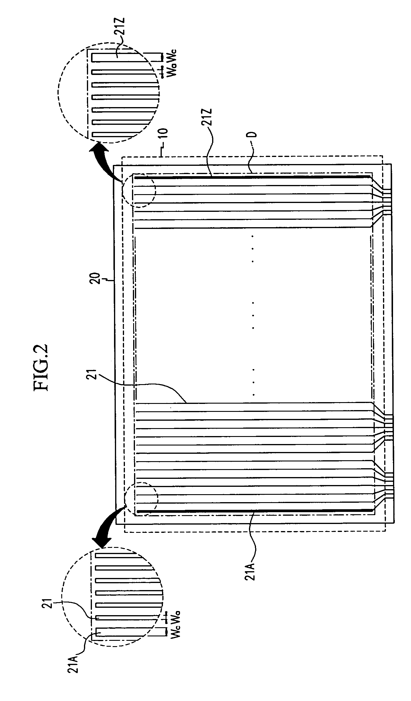
[0030] Turning now to the drawings, with reference to FIG. 7, a conventional AC PDP includes address electrodes 112 formed along one direction (the X-axis direction of the drawing) on the second substrate 110, and a dielectric layer 113 formed on an entire surface of the second substrate 110 covering the address electrodes 112. Over the dielectric layer 113, a plurality of barrier ribs in a stripe pattern are formed between each of the address electrodes 112, and phosphor layers 117 of red, green, and blue are formed between each of the barrier ribs 115.

[0031] Further, display electrodes 102 and 103 comprised of a pair of transparent electrodes 102a and 103a and a pair of bus electrodes 102b and 103b along the direction intersecting the address electrodes 112 (in the Y-axis direction of the drawing) are formed on a surface of the first substrate 100 opposing the second substrate 110. A dielectric layer 106 and an MgO protective layer 108 are formed sequentially covering the display...


PUM


Abstract

The AC plasma display panel (PDP) has electrodes arranged to correspond to each discharge cell between two substrates, address electrodes for the selection of display cells are formed on one substrate, and a pair of display electrodes for display discharge are formed on the other substrate. The plasma display panel includes a first substrate and a second substrate opposing each other; display electrodes formed along one direction on the first substrate, being parallel to one another; address electrodes formed on the second substrate along the direction intersecting the display electrodes, and being parallel to one another; barrier ribs arranged in the space between the first substrate and the second substrate to define a plurality of discharge cells; and phosphor layers formed in each of the discharge cells. Then, expanded portions are formed in the regions of the address electrodes that correspond to the outermost discharge cells adjacent to the edges of both of the substrates.

Description

CROSS REFERENCE TO RELATED APPLICATION [0001] This application relates to a U.S. patent application which is concurrently submitted to the U.S. Patent & Trademark Office with this application, and which is based upon a Korean Priority Serial No. 2003-61838 entitled PLASMA DISPLAY PANEL filed in the Korean Industrial Property Office on 4 Sep. 2003. The related application is incorporated herein by reference in its entirety. CLAIM OF PRIORITY [0002] This application makes reference to, incorporates the same herein, and claims all benefits accruing under 35 U.S.C. §119 from an application for PLASMA DISPLAY PANEL earlier filed in the Korean Intellectual Property Office on 4 Sep. 2003 and there duly assigned Serial No. 2003-61840. BACKGROUND OF THE INVENTION [0003] 1. Field of the Invention [0004] The present invention relates to a plasma display panel (PDP), and more particularly to an AC (Alternating Current) PDP with an electrode configuration, wherein electrodes are arranged to corr...

Claims


Application Information

Patent Timeline
IPC IPC(8): H01J17/49
CPCH01J11/12H01J2211/265H01J11/26
Inventor KWON, JAE-IKKANG, KYOUNG-DOO
Owner SAMSUNG SDI CO LTD
Why Eureka
Try Eureka