Multiphase clock generators

a generator and multi-phase technology, applied in the direction of generating/distributing signals, pulse techniques, instruments, etc., can solve the problems of time variation that can distort data output, half cycle intervals that do not provide enough time to start dividers,

Active Publication Date: 2005-03-10
MICRON TECH INC
View PDF16 Cites 12 Cited by
  • Summary
  • Abstract
  • Description
  • Claims
  • Application Information

AI Technical Summary

Benefits of technology

[0009] For another embodiment, the invention provides a memory device having an array of memory cells and control circuitry for controlling access to the array of memory cells. The control circuitry has a multiphase clock generator. The multiphase clock generator has a first clock divider for generating a first-phase clock signal from a first input clock signal. An input port of the first clock divider is connected to a first inverter. A first logic gate is connected to an output port of the first clock divider. A second clock divider is connected to an output port of the first logic gate through a second inverter. The second clock divider i...

Problems solved by technology

One problem with this is that different type latches can cause timing variations that can distort the data output of the latch system.
However, for rel...

Method used


Image

  • Multiphase clock generators
  • Multiphase clock generators
  • Multiphase clock generators

Examples


Embodiment Construction

[0015] In the following detailed description of the invention, reference is made to the accompanying drawings that form a part hereof, and in which is shown, by way of illustration, specific embodiments in which the invention may be practiced. In the drawings, like numerals describe substantially similar components throughout the several views. These embodiments are described in sufficient detail to enable those skilled in the art to practice the invention. Other embodiments may be utilized and structural, logical, and electrical changes may be made without departing from the scope of the present invention. The following detailed description is, therefore, not to be taken in a limiting sense, and the scope of the present invention is defined only by the appended claims and equivalents thereof.

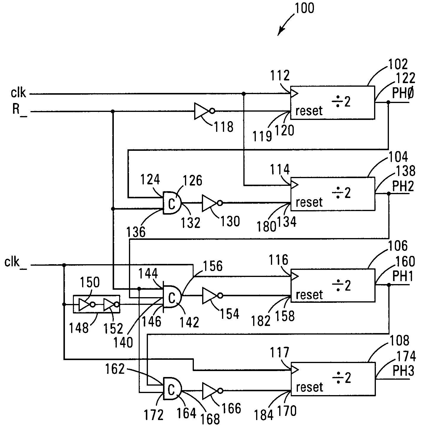
[0016]FIG. 1 illustrates a multiphase clock generator 100 according to an embodiment of the present invention. Clock generator 100 has clock dividers 102, 104, 106, and 108. For one embodiment...


PUM


Abstract

Multiphase clock generators and methods are provided. A multiphase clock generator has a first clock divider for generating a first-phase clock signal from a first input clock signal. A first logic gate is connected to an output port of the first clock divider. A second clock divider is connected to an output port of the first logic gate. The second clock divider is for generating a second-phase clock signal from the first input clock signal. A second logic gate is connected to an output port of the second clock divider. A third clock divider is connected to an output port of the second logic gate. The third clock divider is for generating a third-phase clock signal from a second input clock signal.

Description

TECHNICAL FIELD OF THE INVENTION [0001] The present invention relates generally to clock generators and in particular the present invention relates to multiphase clock generators. BACKGROUND OF THE INVENTION [0002] Clock signals are used for timing or synchronizing operations within many electronic devices. For example, clock signals are used for timing or synchronizing read and write operations for memories, such as flash memories, dynamic random access memories (DRAMs), static random access memories (SRAMs), etc., of electronic devices, such as desktop or portable computers. For some applications, clock signals are used to control data latching for read and write applications. For one application, such as for double-data-rate DRAMs, it is advantageous to latch data, for example, every half-clock cycle. This typically involves using a first latch of a latch system to latch data when the clock signal goes from low to high, i.e., on a positive clock transition (or positive clock edge...

Claims


Application Information

Patent Timeline
IPC IPC(8): G06F1/06
CPCG06F1/06G11C7/22H03K2005/00286H03K5/15013G11C7/222
Inventor JOHNSON, BRIAN
Owner MICRON TECH INC
Why Eureka
Try Eureka