Driving circuit and driving method for LCD

Inactive Publication Date: 2005-03-10
TRIVALE TECH
View PDF7 Cites 10 Cited by
  • Summary
  • Abstract
  • Description
  • Claims
  • Application Information

AI Technical Summary

Benefits of technology

[0007] Therefore, an object of the present invention is to provide a driving circuit and a driving method for LCD having high displaying quality for moving images by accelerating response of liquid crystal material.
[0008] Another object of the present invention is to provide a driving circuit and a driving method for LCDs which can obtain high displaying quality for moving images with accelerating response of liquid crystal material within a limited memory and circuit scale.

Problems solved by technology

However, it requires relatively long time for a liquid crystal material in certain orientation to be changed into another orientation according to the newly applied voltage.
Therefore, in case of displaying object which moves at high-speed, there is a problem which causes afterimage and blurred image since the liquid crystal material can not reach the desired orientation during the “one field period”.

Method used


Image

  • Driving circuit and driving method for LCD
  • Driving circuit and driving method for LCD
  • Driving circuit and driving method for LCD

Examples


embodiment 1

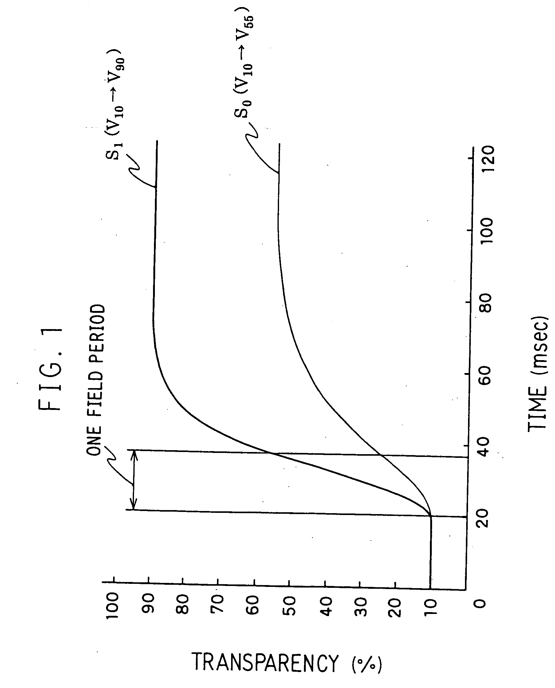
[0036] The description of the first embodiment of the present invention will be given with referring to FIG. 1.

[0037]FIG. 1 shows a relation between an applied voltage and a transparency in a pixel with presenting time (msec) in horizontal axis and transparency (%) in vertical axis. A displayed image is refreshed by a frequency of 60 Hz in most LCDs, so one field period is approximately 16.6 msec in FIG. 1. In FIG. 1, the transparency in a pixel is 10% in preceding field (until 20 msec) and to be changed to 55% in the following current field.

[0038] In the prior art LCDs, as presented by thin line S0 in FIG. 1, a voltage with which the transparency of 55% can be obtained after plenty of time to complete response of liquid crystal material (hereinafter referred as V55) is applied. Thus, the transparency in a pixel shall not reach 55% during the current field, thereby deteriorating the displaying quality for moving image.

[0039] In the present invention, however, a voltage with which...

embodiment 2

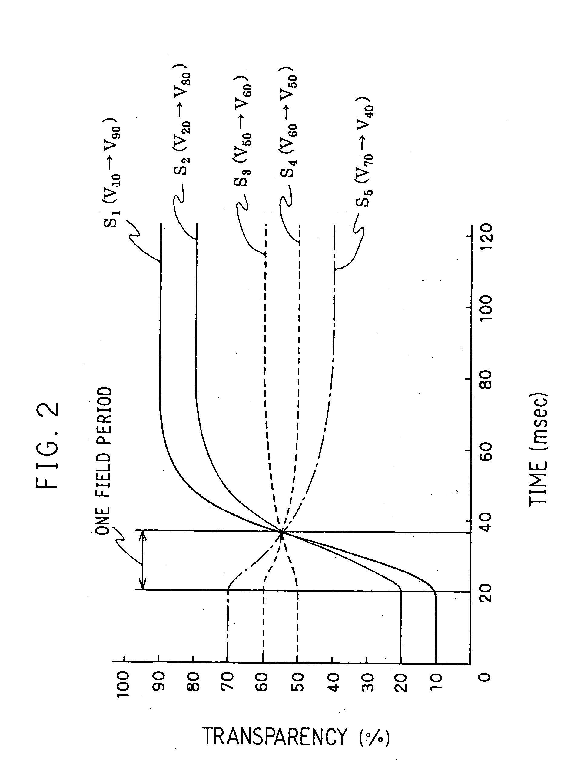
[0041]FIG. 2 shows a relation between applied voltage and the transparency in a pixel with presenting time in horizontal axis and transparency in vertical axis. In FIG. 2, required voltages at the current field to obtain a desired transparency of 55% are shown in correspondence with various transparencies in preceding field. When the transparency of the preceding field is 20%, applying a voltage of V80, i.e. a voltage whereby transparency of the pixel at the completion of response of liquid crystal material becomes 80%, enables to obtain the transparency of 55% at the end of the current field. Similarly, with each of the transparency of 50%, 60% and 70% of the preceding field, applying a voltage of V60, V50 and V40 enable to achieve the desired transparency of 55% at the end of the current field.

[0042] Thus, a voltage for obtaining desired transparency at the end of the field can be determined by the transparency at the preceding field uniquely. Therefore, it is possible to obtain ...

embodiment 3

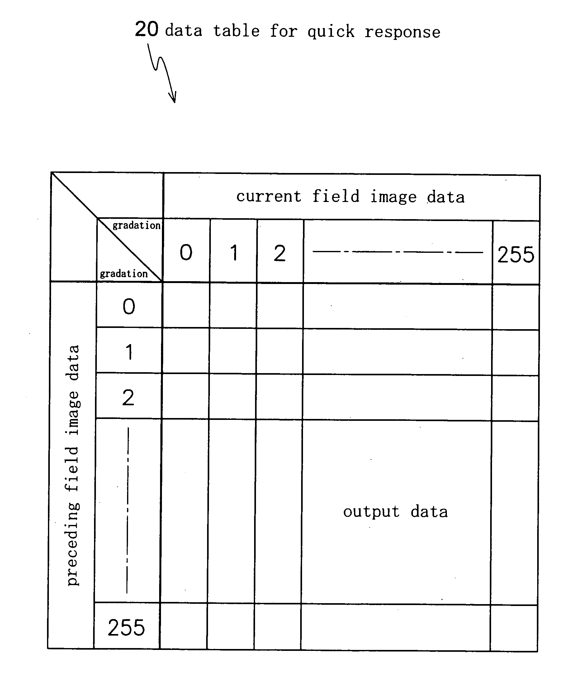
[0049] The third embodiment of the present invention will be described with referring to FIGS. 5, 6, 7, 8 and 9. In the present embodiment, a data table for quick response has output data of 256 gradations in correspondence with the preceding and current field image data of 8 gradations selected from 256 gradations. Therefore the required size of data table for quick response is only 64 byte thereby enables to reduce the amount of memory and the number of data line connected to a processor.

[0050] Hereinafter, the operation of a driving circuit according to the present embodiment will be described with attached flow chart. Due to limitations of space, the flow chart is divided into two sheets, i.e. FIG. 5 and FIG. 6, at the points marked with “*1”, “*2”and “*3”.

[0051] Firstly, a frame memory is initialized at step S101, and the image data from a signal source is stored temporally. At this time it is possible to reduce the size of frame memory by storing converted image data in whic...


PUM


Abstract

The present invention is directed to provide a driving circuit and driving method for a LCD having high performance of moving image displaying within few amount of memory and downscaled circuit. In the present invention, a voltage applied to a pixel to drive liquid crystal material in the pixel is determined as a voltage with which the transparency of the pixel at the end of the current field becomes the designated transparency. To determine the voltage, a data table for quick response in which output data is stored in correspondence with some of the possible value of a preceding field image data and some of the possible value of the current field image data is employed, and the output data corresponding to the preceding field image data and the current field image data is determined by the data table through linear interpolation. The voltage corresponding to the output data is applied to the pixel.

Description

BACKGROUND OF THE INVENTION [0001] The present invention relates to a LCD (Liquid Crystal Display), more particularly, to a driving circuit and driving method for a LCD. [0002] LCDs have many pixels arranged in rows and columns in their screen. Each pixel has its own electrode, i.e. pixel electrode, for applying a voltage to a liquid crystal material in that pixel. By selecting a row of pixels, the voltages are applied to the pixel electrodes in the selected row through column signal lines. Selecting all the rows sequentially, all the pixel electrodes in the screen are supplied with their own voltages. Through these voltages, the liquid crystal material in each pixel is driven and changes its orientation, thereby the amount of light passing through each pixel is controlled so that an image is displayed on the screen. [0003] Meanwhile, it should be noted that LCDs typically have a common electrode which is commonly owned by all pixels, and to be precise, the voltage difference betwee...

Claims


Application Information

Patent Timeline
IPC IPC(8): G02F1/133G09G3/20G09G3/36
CPCG09G3/20G09G3/3611G09G2340/16G09G2320/0285G09G2320/0261G09G3/36
Inventor ODA, KYOICHIROYUUKI, AKIMASATAHATA, SHINTOBITA, TOSHIOMIYAKE, SHIROKOBAYASHI, KAZUHIROMURAYAMA, KEIICHI
Owner TRIVALE TECH
Why Eureka
Try Eureka