
Selective input system based on tracking of motion parameters of an input device

a technology of input device and motion parameter, which is applied in the field of input device and user interface, can solve the problems of difficult operation, prone to errors, and difficulty in performing selective pointing functions, and achieve the effect of improving accuracy and usability of the input system

Active Publication Date: 2005-03-10
TEGIC COMM
View PDF99 Cites 162 Cited by
  • Summary
  • Abstract
  • Description
  • Claims
  • Application Information

AI Technical Summary

Benefits of technology

"The patent describes a system and method that track the movement of an input device (like a touchpad, mouse, or pen) over a printed or virtual keyboard. The system uses sensors to detect the motion of the input device and identify selections on the keyboard by detecting parameters of motion like length, direction, velocity, and lack of motion. This system is also connected to a text disambiguation system to improve accuracy and usability. The technical effect of this patent is to provide a more efficient and accurate way to input text on devices with touchpads or keyboards."

Problems solved by technology

A user is often required to perform a large number of selective pointing actions, which can be difficult to perform, and are prone to error.
Furthermore, the user interfaces for many devices are often small, such as for small electronic devices, e.g. portable cell phones, personal digital assistants (PDAs), or other devices often used for business, personal, educational, or recreational purposes.
The selective pointing functions required to operate such small devices have become increasingly difficult and prone to error, as a user must accurately tap on a very small region within a user interface.
While such entry systems provide a means for entering information, the required shorthand or stylus paths are often complex, and movements required for one character are easily mistaken for different characters.

Method used


Image

  • Selective input system based on tracking of motion parameters of an input device
  • Selective input system based on tracking of motion parameters of an input device
  • Selective input system based on tracking of motion parameters of an input device

Examples


Embodiment Construction

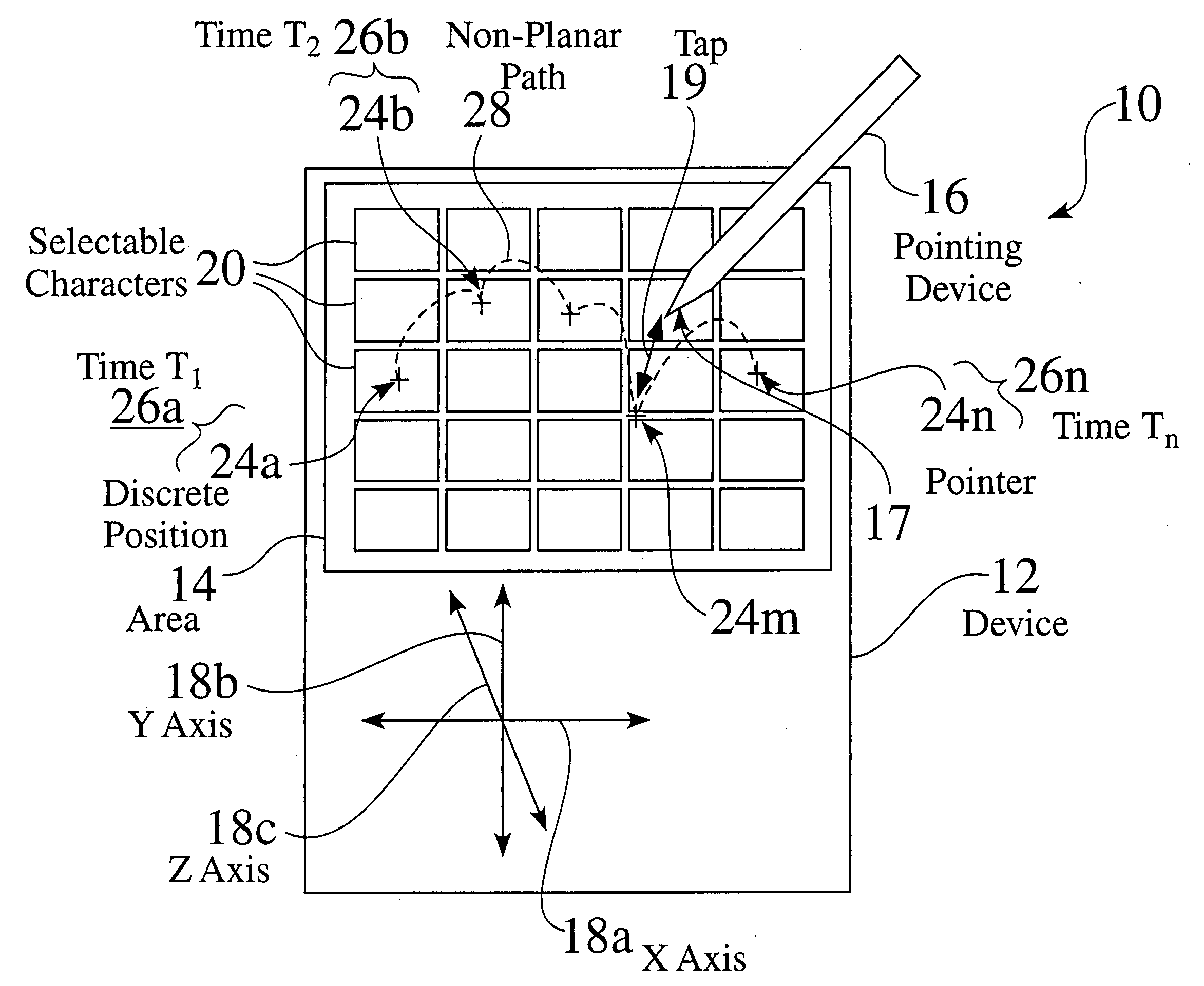
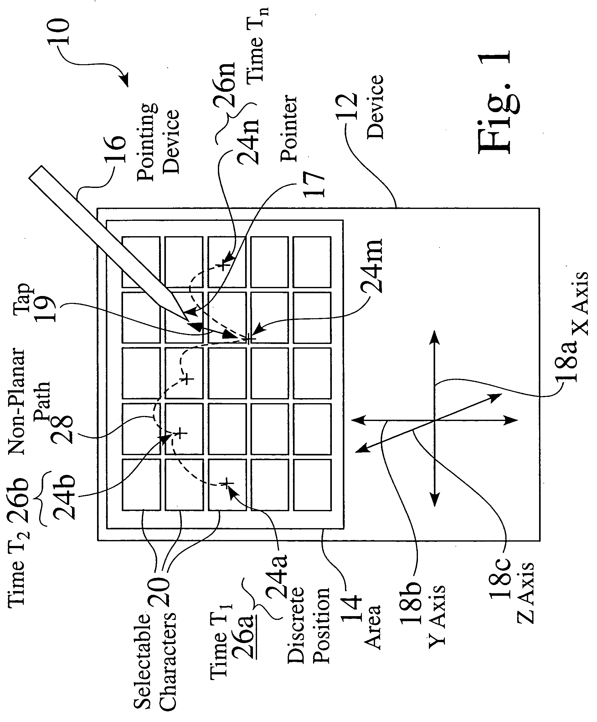
[0033]FIG. 1 is a schematic view of a user input system 10, in which discrete positions of a pointing device, i.e. instrument 16 within an input area 14 are determined. Devices 12 often comprise means 16 for pointing or selecting, such as by a stylus, finger, or mouse, whereby a user may interact with a device 12. The user is often required to interact with a user interface area 14, such as a keypad, touchpad, or touch screen, such as to input a desired character 20.

[0034] In the user input system 10 shown in FIG. 1, a user typically maneuvers the pointing or selection device 16 over a desired position 24, e.g. 24a, over the interface area 14, and then taps or sets 19 the pointing device 16, such as by contacting a pointing tip or pointer 17 to a desired location 24 within an interface area 14, to activate a chosen region or element, e.g. such as an actual or mapped keypad element or character 20.

[0035] As described above, a user is often required to perform a large number of sele...


PUM


Abstract

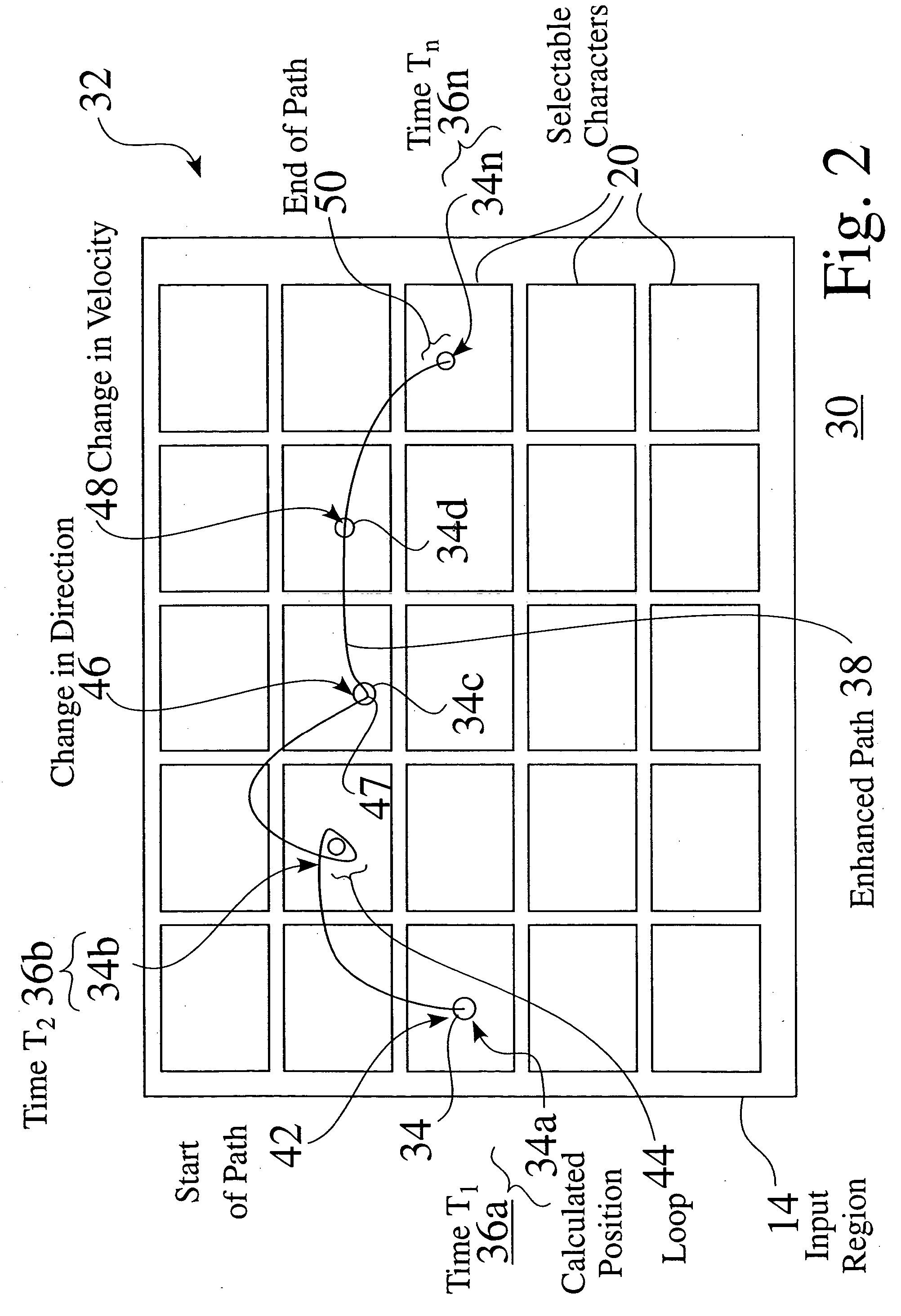
A selective input system and associated method is provided which tracks the motion of a pointing device over a region or area. The pointing device can be a touchpad, a mouse, a pen, or any device capable of providing two or three-dimensional location. The region or area is preferably augmented with a printed or actual keyboard / pad. Alternatively, a representation of the location of the pointing device over a virtual keyboard / pad can be dynamically shown on an associated display. The system identifies selections of items or characters by detecting parameters of motion of the pointing device, such as length of motion, a change in direction, a change in velocity, and or a lack of motion at locations that correspond to features on the keyboard / pad. The input system is preferably coupled to a text disambiguation system such as a T9® or Sloppytype™ system, to improve the accuracy and usability of the input system.

Description

CROSS REFERENCE TO RELATED APPLICATIONS [0001] This Application also claims priority for U.S. Provisional Patent Application Ser. No. 60 / 504,552, entitled SELECTIVE INPUT SYSTEM BASED ON TRACKING OF MOTION PARAMETERS OF AN INPUT DEVICE, US Filing Date 19 Sep. 2003. [0002] This Application is a Continuation In Part of U.S. patent application Ser. No. 10 / 677,890 (TEGI0013), entitled DIRECTIONAL INPUT SYSTEM WITH AUTOMATIC CORRECTION, US Filing Date 01 Oct. 2003, which claims priority to U.S. patent application Ser. No. 10 / 205,950, filed 25 Jul. 2002; to U.S. patent application Ser. No. 09 / 580,319 filed 26 May 2000, entitled KEYBOARD SYSTEM WITH AUTOMATIC CORRECTION; and to U.S. Provisional Patent Application Ser. No. 60 / 461,735, filed 09 Apr. 2003.FIELD OF THE INVENTION [0003] The invention relates to input devices and user interfaces. More particularly, the invention relates to the tracking of the position and / or motion of an input device and selection of items or character input bas...

Claims


Application Information

Patent Timeline
Patent Type & Authority Applications(United States)
IPC IPC(8): G06FG06F3/023G06F3/033G06F3/048G09G5/00
CPCG06F3/0236G06F3/04886G06F3/04883
Inventor STEPHANICK, JAMESJAMES, CHRISTINABRADFORD, ETHAN R.LONGE, MICHAEL R.
Owner TEGIC COMM
Learn More