
Liquid discharge apparatus and inkjet recording apparatus

Inactive Publication Date: 2005-03-10
FUJIFILM CORP
View PDF3 Cites 6 Cited by
  • Summary
  • Abstract
  • Description
  • Claims
  • Application Information

AI Technical Summary

Benefits of technology

The present invention has been implemented taking into account the above described circumstances, and an object thereof is to provide a liquid discharge apparatus that can realize stable liquid discharge by controlling the liquid physical properties in the vicinity of the nozzles, can realize rapid refilling even with a high-viscosity ink, and can also maintain discharge and refilling performances, and an inkjet recording apparatus that uses this liquid discharge apparatus.
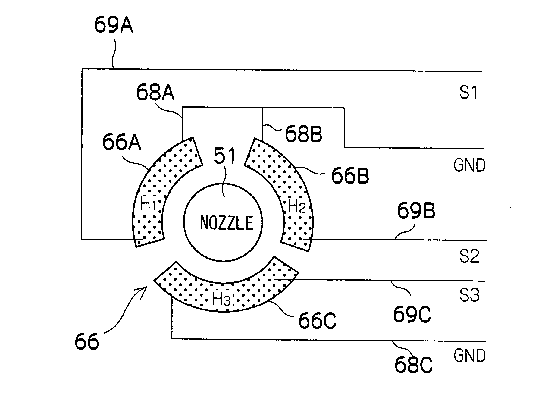
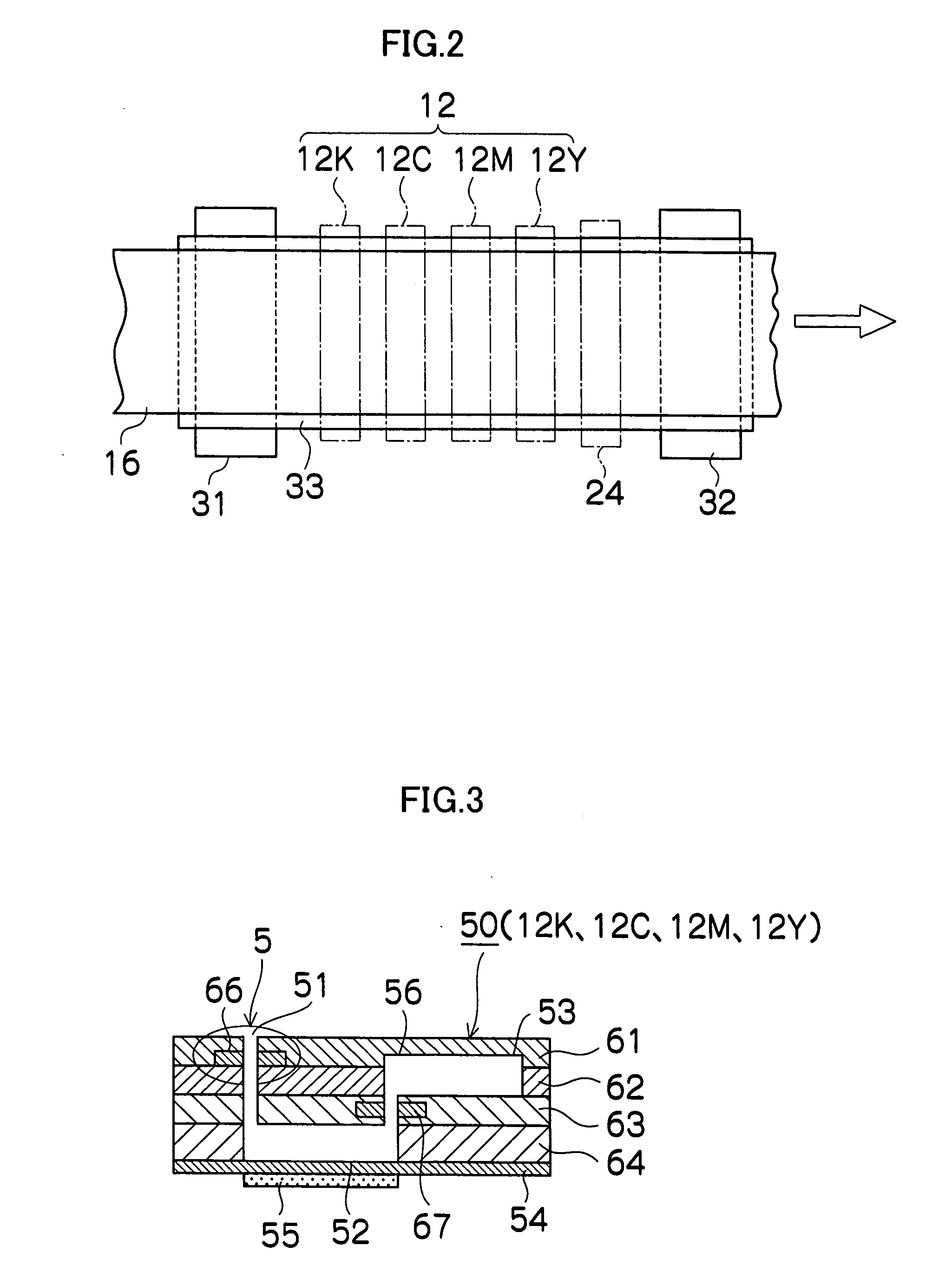
A relatively large distance can be provided between the heating devices, and mutual temperature effects can be avoided with an aspect in which the nozzles, pressure chambers, common flow channel, and supply channels, which are required components for liquid discharge in the present invention, are formed of a laminated structure, and a nozzle-portion heating device and a supply-channel heating device are provided to a plate member (flow channel plate) with different layers. Therefore, heat can be transmitted to solely the area around the nozzles and the area around the supply channels (the area around the individual flow channels), and the effect of adjusting the temperature of the liquid can be maintained.

Problems solved by technology

The inkjet recording apparatuses stop discharging ink or experience other discharge defects when the viscosity of the ink increases inside the nozzles due to drying or the like.
Nevertheless, the method proposed in Japanese Patent Application Publication No. 11-10878 has a structure in which thermal heaters are disposed in close proximity at intervals of several tens of micrometers on the discharge side and supply side with respect to the ink flow channel in the same plane, so there is a drawback in that as the number of discharges increases, the temperature difference between these two heaters grows smaller, and the effect of higher discharge strength is lessened.
The thermal heater is disposed in a very close positional relationship forward and rearward of this heater, so there is a drawback in that the temperature difference between the heaters is even smaller.

Method used


Image

  • Liquid discharge apparatus and inkjet recording apparatus
  • Liquid discharge apparatus and inkjet recording apparatus
  • Liquid discharge apparatus and inkjet recording apparatus

Examples


Embodiment Construction

General Configuration of an Inkjet Recording Apparatus

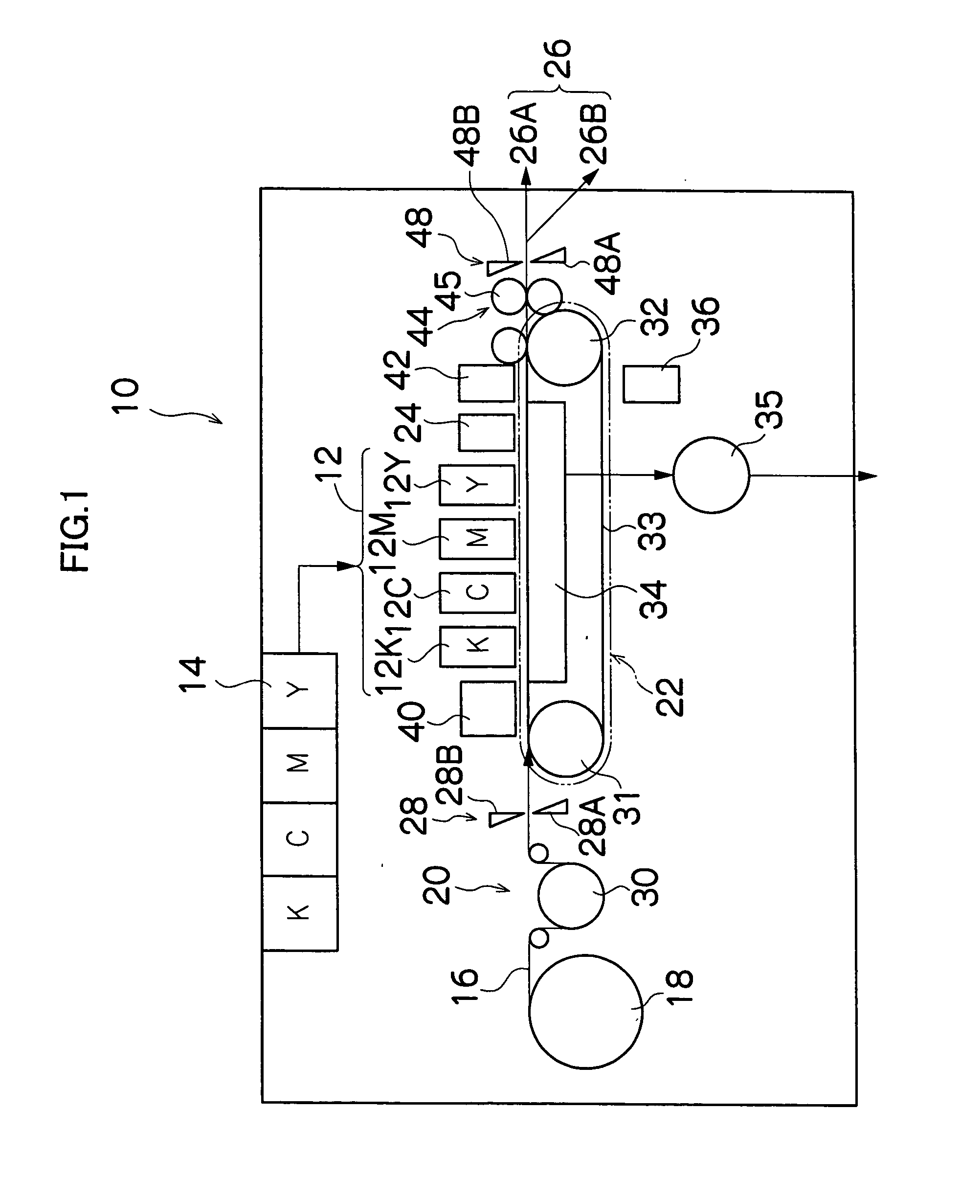
FIG. 1 is a general schematic drawing of an inkjet recording apparatus according to an embodiment of the present invention. As shown in FIG. 1, the inkjet recording apparatus 10 comprises: a printing unit 12 having a plurality of print heads 12K, 12C, 12M, and 12Y for ink colors of black (K), cyan (C), magenta (M), and yellow (Y), respectively; an ink storing / loading unit 14 for storing inks to be supplied to the print heads 12K, 12C, 12M, and 12Y; a paper supply unit 18 for supplying recording paper 16; a decurling unit 20 for removing curl in the recording paper 16; a suction belt conveyance unit 22 disposed facing the nozzle face (ink-droplet ejection face) of the print unit 12, for conveying the recording paper 16 while keeping the recording paper 16 flat; a print determination unit 24 for reading the printed result produced by the printing unit 12; and a paper output unit 26 for outputting image-printed recording paper (pr...


PUM


Abstract

The liquid discharge apparatus discharges liquid from an orifice of a nozzle portion, and comprises: a nozzle-portion heating device which heats the nozzle portion; and a nozzle heating control device which controls a heating timing by the nozzle-portion heating device in accordance with a discharge drive timing for discharging the liquid from the orifice of the nozzle portion.

Description

BACKGROUND OF THE INVENTION 1. Field of the Invention The present invention relates to a liquid discharge apparatus and an inkjet recording apparatus, and more particularly to a structure for a discharge head suitable for realizing a stable liquid discharge and a technology of drive control thereof. 2. Description of the Related Art Inkjet recording apparatuses deposit ink droplets on a recording medium by relatively moving recording paper or another recording medium with respect to a recording head provided with ink discharge nozzles while discharging ink from the recording head in accordance with a print signal, and an image is formed on the printing medium by the ink dots. The inkjet recording apparatuses stop discharging ink or experience other discharge defects when the viscosity of the ink increases inside the nozzles due to drying or the like. The resupply performance (refill performance) of ink to the nozzles is reduced when the ink viscosity increases. In view of the a...

Claims


Application Information

Patent Timeline
IPC IPC(8): B41J2/045
CPCB41J2/04528B41J2/04571B41J2/04588B41J2/04581B41J2/0458
Inventor KODAMA, KENICHI
Owner FUJIFILM CORP
Learn More