Liquid discharge method, liquid discharge head, liquid discharge apparatus, and method for manufacturing liquid discharge head
a liquid discharge head and liquid discharge technology, applied in printing and other directions, can solve the problems of large loss of discharge energy, long tail, and valve on the discharge port side of the bubble, and achieve the effect of reducing the risk of satellites and satellites, and reducing the discharge energy of liquid discharg
- Summary
- Abstract
- Description
- Claims
- Application Information
AI Technical Summary
Benefits of technology
Problems solved by technology
Method used
Image
Examples
first embodiment
(First Embodiment)
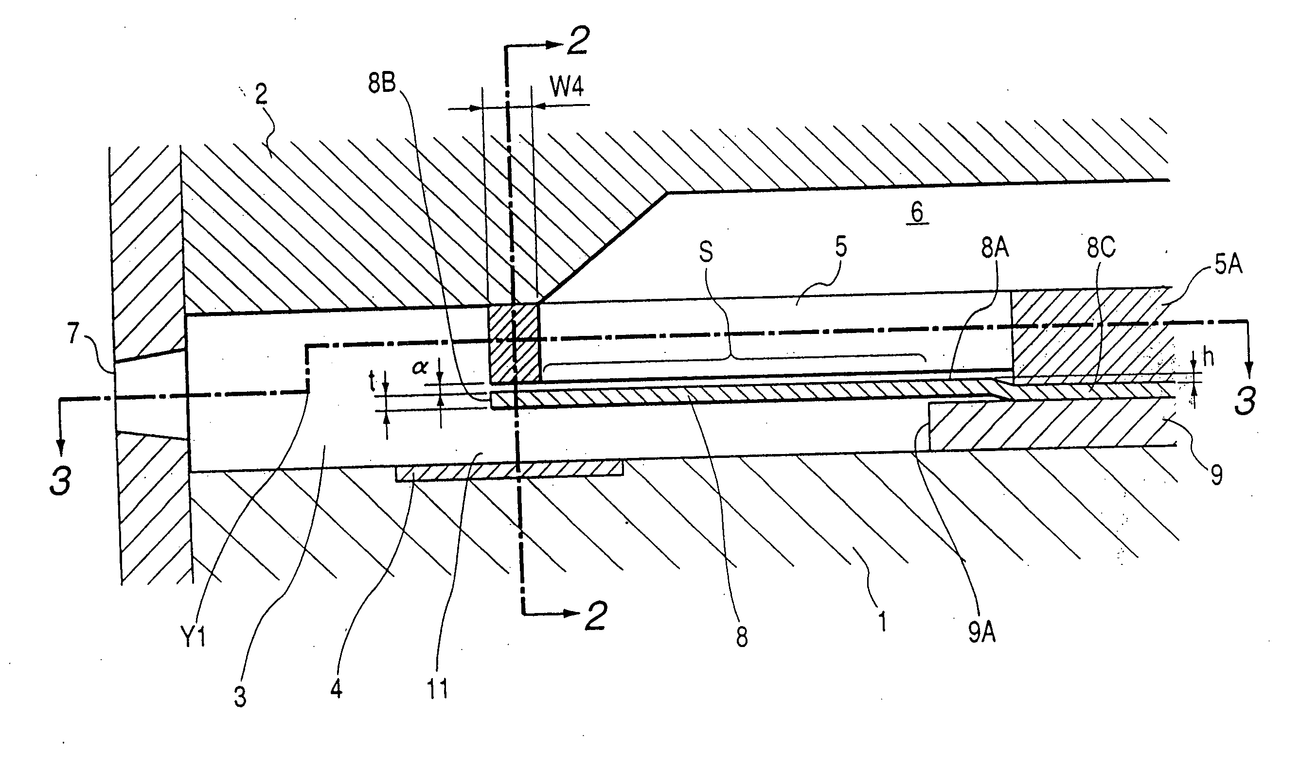
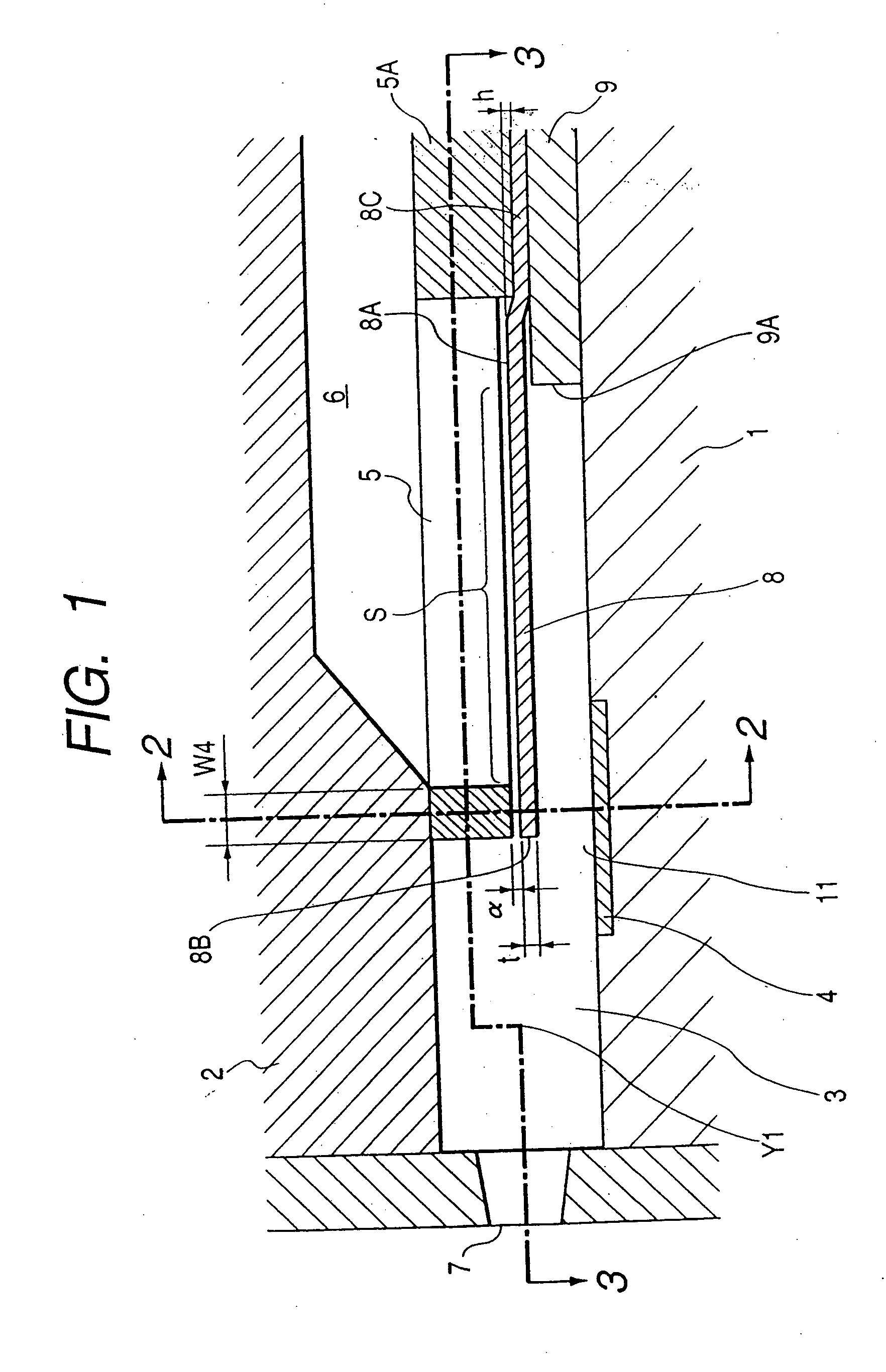
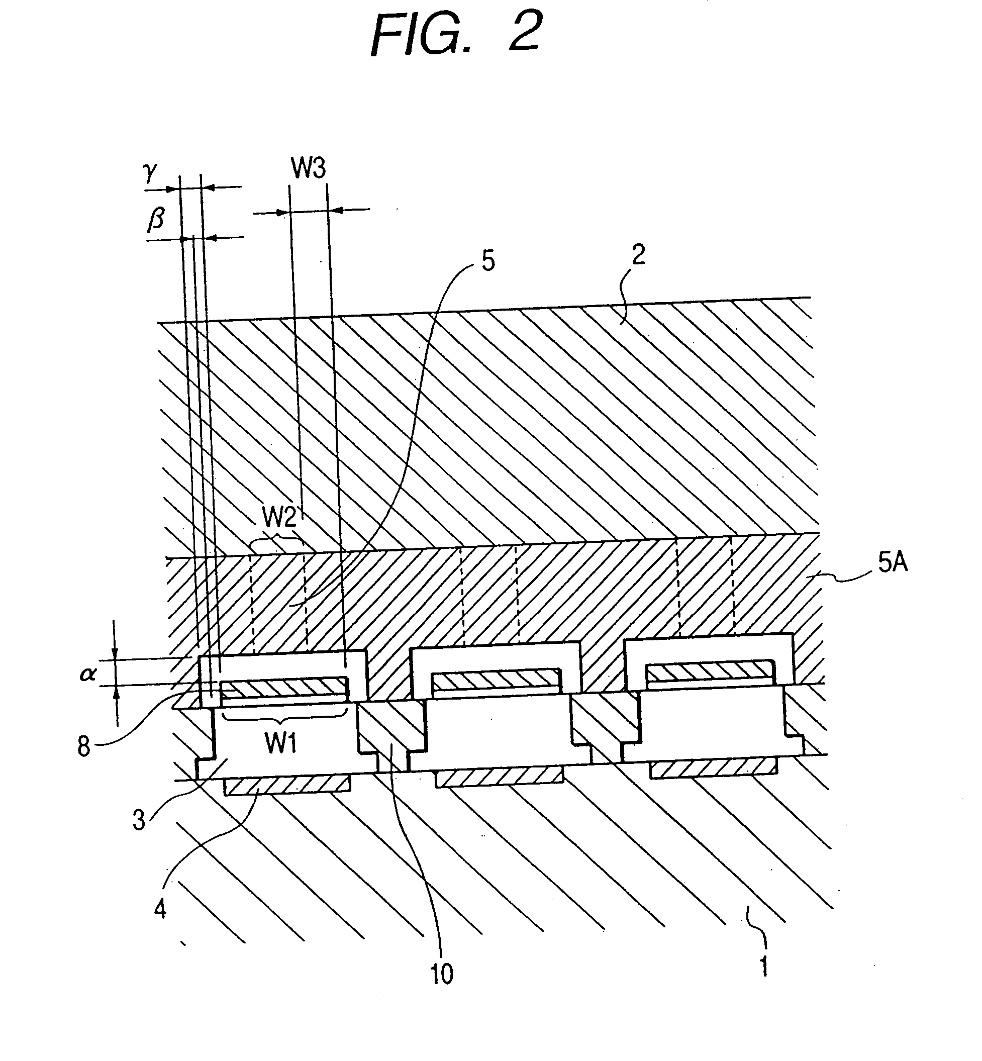
FIG. 1 is a cross-sectional view which shows a liquid discharge head in accordance with a first embodiment of the present invention, taken in the direction of one liquid flow path. FIG. 2 is a cross-sectional view taken along line 2-2 in FIG. 1. FIG. 3 is a cross-sectional view taken along line 3-3 in FIG. 1, which shows a shift from the center of the discharge port to the ceiling plate 2 side at a pint Y1.
For the liquid discharge head shown in FIG. 1 to FIG. 3, which is in the mode of plural liquid paths—a common liquid chamber, the elemental base plate 1 and the ceiling plate 2 are fixed in a state of being laminated through the liquid path side walls 10. Then, between both plates 1 and 2, a liquid flow path 3 is formed, one end of which is communicated with the discharge port 7. This flow path 3 is arranged in plural numbers for one head. Also, on the elemental base plate 1, there is arranged for each of the liquid flow paths 3, the heat generating element 4, ...
second embodiment
(Second Embodiment)
For the head structure of the first embodiment, the position of the foot supporting member 8C of the movable member 8, which is not to be in contact with the fixing member 9 (that is, bent to rise) as shown in FIGS. 1 to 3, is not the same as the edge portion 9A of the fixing member 9. Therefore, the opening area S becomes the area surrounded by the three sides of the liquid supply port 5 and the edge portion 9A of the fixing member 9. However, as shown in FIGS. 12, 13, it may be possible to adopt a mode in which the position of the foot supporting member 8C of the movable member 8 being bent to rise from the fixing member 9 is set at the edge portion 9A of the fixing member 9. In the case of this mode, the opening area S becomes the area surrounded by the three sides of the liquid supply port 5 and the fulcrum 8A of the movable member 8 as shown in FIGS. 12 and 13.
Also, as shown in FIG. 3, the liquid supply port 5 is arranged to be an opening surrounded by fou...
third embodiment
(Third Embodiment)
Further, for each of the embodiments described above, it is more preferable to make the thickness t of the movable member 8 larger than the stepping amount h of the foot supporting member 8C of the movable member 8 as shown in FIGS. 1, 12, or FIG. 14, for example. Here, it is arranged to set the t=5 μm, and the h=2 μm, for example. With this arrangement, it becomes possible to relax the stress concentration which is concentrated on the stepping portion of the foot supporting member 8C of the movable member 8 when the movable member 8 is displaced, hence improving the durability of the foot portion of the movable member 8.
Also, FIG. 16 is an enlarged sectional view which shows the circumference of the foot portion of the movable member in accordance with the head structure represented in FIG. 12. FIG. 17 shows the variational example of the one shown in FIG. 16.
As represented in FIG. 16, the height position of the movable member 8 for each of the embodiments de...
PUM
 Abstract
Description
Claims
Application Information
 - R&D
- Intellectual Property
- Life Sciences
- Materials
- Tech Scout
- Unparalleled Data Quality
- Higher Quality Content
- 60% Fewer Hallucinations
Browse by: Latest US Patents, China's latest patents, Technical Efficacy Thesaurus, Application Domain, Technology Topic, Popular Technical Reports.
© 2025 PatSnap. All rights reserved.Legal|Privacy policy|Modern Slavery Act Transparency Statement|Sitemap|About US| Contact US: help@patsnap.com


