Liquid crystal display device

a display device and liquid crystal technology, applied in static indicating devices, instruments, non-linear optics, etc., can solve the problem of limited degree of freedom in manufacturing backlights, and achieve the effect of increasing the degree of freedom of backlights or the like, and increasing the intensity of ligh

Active Publication Date: 2005-03-10
PANASONIC LIQUID CRYSTAL DISPLAY CO LTD +1
View PDF0 Cites 91 Cited by
  • Summary
  • Abstract
  • Description
  • Claims
  • Application Information

AI Technical Summary

Benefits of technology

[0012] The present invention has been made under such circumstances and it is one of advantages of the invention to provide a liquid crystal display device which can enhance the degree of freedom in manufacturing a backlight and the like.
[0027] Further, although the pixels which decrease the light transmitting quantity or the numerical aperture are present in the unit pixel for color display, the number of light emitting elements of color corresponding to such pixels is increased and hence, the intensity of light is increased thus obviating the occurrence of drawbacks from this point of view.
[0028] Accordingly, due to the above-mentioned constitution, to the contrary, when it is necessary to arbitrarily set the number of light emitting elements of respective colors used as the light source, it is sufficient to change the light transmitting quantities or the numerical apertures of the pixels allocated to respective colors and hence, the degree of freedom of the backlight or the like can be increased.

Problems solved by technology

Accordingly, in forming the backlight, the degree of freedom in manufacturing the backlight is limited and there has been a strong demand for the measure to overcome such a drawback.

Method used


Image

  • Liquid crystal display device
  • Liquid crystal display device
  • Liquid crystal display device

Examples


Embodiment Construction

[0063] Preferred embodiments of liquid crystal display devices according to the invention are explained in detail in conjunction with drawings.

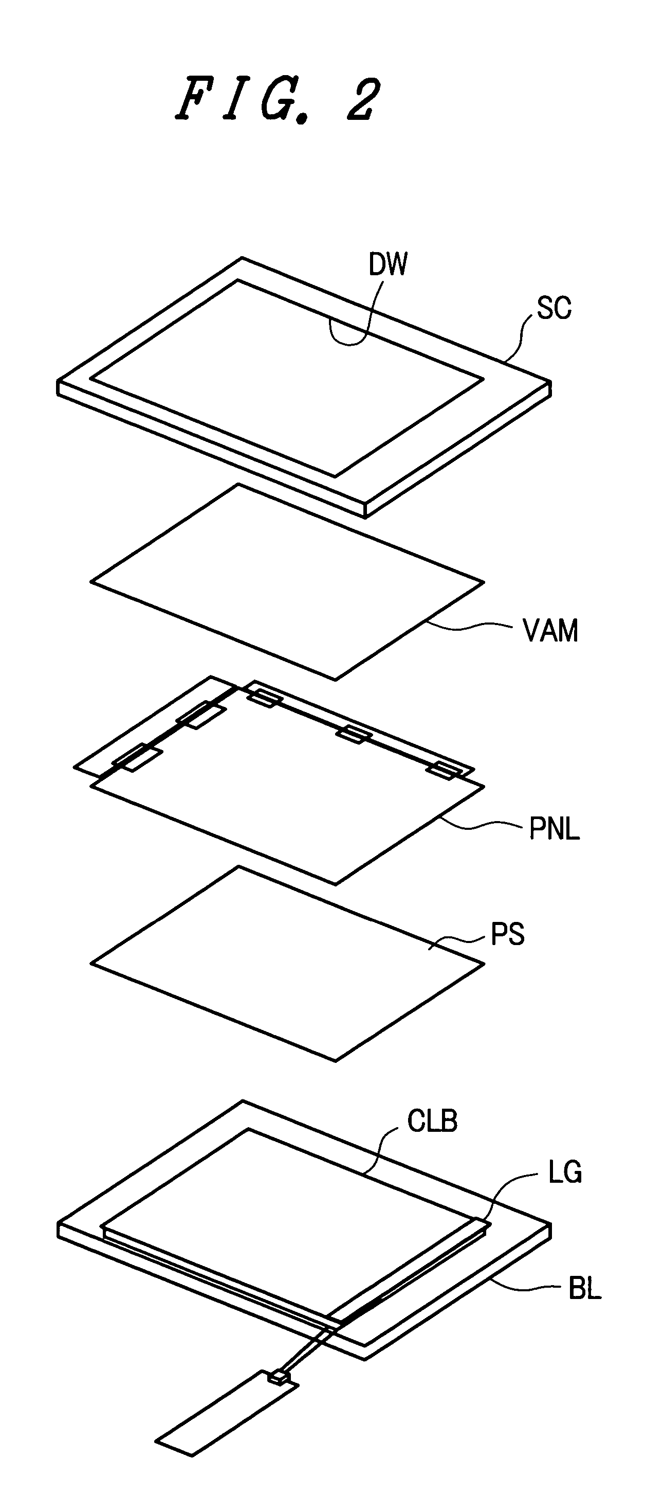
[0064]FIG. 2 is an exploded perspective view of the liquid crystal display device according to the invention which is formed into a module.

[0065] As shown in FIG. 2, the liquid crystal display device is constituted by integrally stacking a shielding case SC, a viewing angle magnification film VAM, a liquid crystal display panel PNL, a prism sheet PS and a backlight BL.

[0066] Here, the shielding case SC is a frame body which forms a display window DW on a portion thereof which faces a display part of the liquid crystal display panel PNL. By fixing a periphery of the shielding case SC to the backlight BL, the viewing angle magnification film VAM, the liquid crystal display panel PNL and the prism sheet PS can be incorporated in a space defined by the shielding case SC and the backlight BL.

[0067] Further, the backlight BL includes at least a...


PUM

PropertyMeasurementUnit
capacitanceaaaaaaaaaa
colorsaaaaaaaaaa
electric fieldaaaaaaaaaa

Abstract

A liquid crystal display device includes a liquid crystal display panel having respective pixels which are allocated to red, green and blue and a light source which allows light to pass through the respective pixels, wherein the light source is constituted of a plurality of red light emitting elements, a plurality of green light emitting elements and a plurality of blue light emitting elements. The liquid crystal display device further includes pixels which have the largest light transmitting quantity out of the respective pixels allocated to red, green and blue, and the number of light emitting elements of color corresponding to color which is allocated to the pixels having the largest light transmitting quantity is smaller than the number of light emitting elements of other color.

Description

BACKGROUND OF THE INVENTION [0001] 1. Field of the Invention [0002] The invention relates to a liquid crystal display device, and more particularly to a liquid crystal display device which is constituted of at least a liquid crystal display panel for color display and a backlight. [0003] 2. Description of the Related Art [0004] A liquid crystal display panel is configured such that liquid crystal is provided between respective substrates which are arranged to face each other in an opposed manner and a large number of pixels are arranged in the spreading direction of the liquid crystal. [0005] Here, each pixel includes means to independently generate an electric field at a portion thereof and the optical transmissivity of the liquid crystal in the pixel is controlled based on the electric field. [0006] Accordingly, usually, a backlight is arranged on a back surface of the liquid crystal display panel and a viewer can observe light from the backlight through the respective pixels. [00...

Claims


Application Information

Patent Timeline
Patent Type & Authority Applications(United States)
IPC IPC(8): F21V8/00G02F1/133G02F1/13357G02F1/1335G02F1/1343G02F1/136G02F1/1368H01L21/336H01L21/8234H01L27/08H01L27/088H01L29/786
CPCG02B6/0068G02F1/134336G02F1/133615G02F1/133603
Inventor OCHIAI, TAKAHIROYANAGAWA, KAZUHIKO
Owner PANASONIC LIQUID CRYSTAL DISPLAY CO LTD
Why Eureka
Try Eureka