Method and system for optically tracking a target using a triangulation technique

a triangulation and target technology, applied in the field of optical systems, can solve the problems of limited resolution of the technology, affecting the use of the computer system, and limiting the potential benefits of the system and device,

Inactive Publication Date: 2005-03-10
AVAGO TECH INT SALES PTE LTD
View PDF16 Cites 61 Cited by
  • Summary
  • Abstract
  • Description
  • Claims
  • Application Information

AI Technical Summary

Problems solved by technology

Although improvements in these systems and devices enhance the usability of computer systems, several deficiencies in the technologies implemented by these systems and devices continue to limit the potential benefits of these systems and devices.
For example, technologies that have a limited resolution hinder use of the computer system.
Moreover, the response time of some of these technologies can be slow.
Moreover, power consumption issues arise in certain technologies.
Lastly, the size required for systems or devices to implement s

Method used


Image

  • Method and system for optically tracking a target using a triangulation technique
  • Method and system for optically tracking a target using a triangulation technique
  • Method and system for optically tracking a target using a triangulation technique

Examples


Embodiment Construction

[0017] Reference will now be made in detail to embodiments in accordance with the invention, examples of which are illustrated in the accompanying drawings. While the invention will be described in conjunction with these embodiments, it will be understood that they are not intended to limit the invention to these embodiments. On the contrary, the invention is intended to cover alternatives, modifications and equivalents, which may be included within the spirit and scope of the invention as defined by the appended claims. Furthermore, in the following detailed description of embodiments in accordance with the invention, numerous specific details are set forth in order to provide a thorough understanding of the invention.

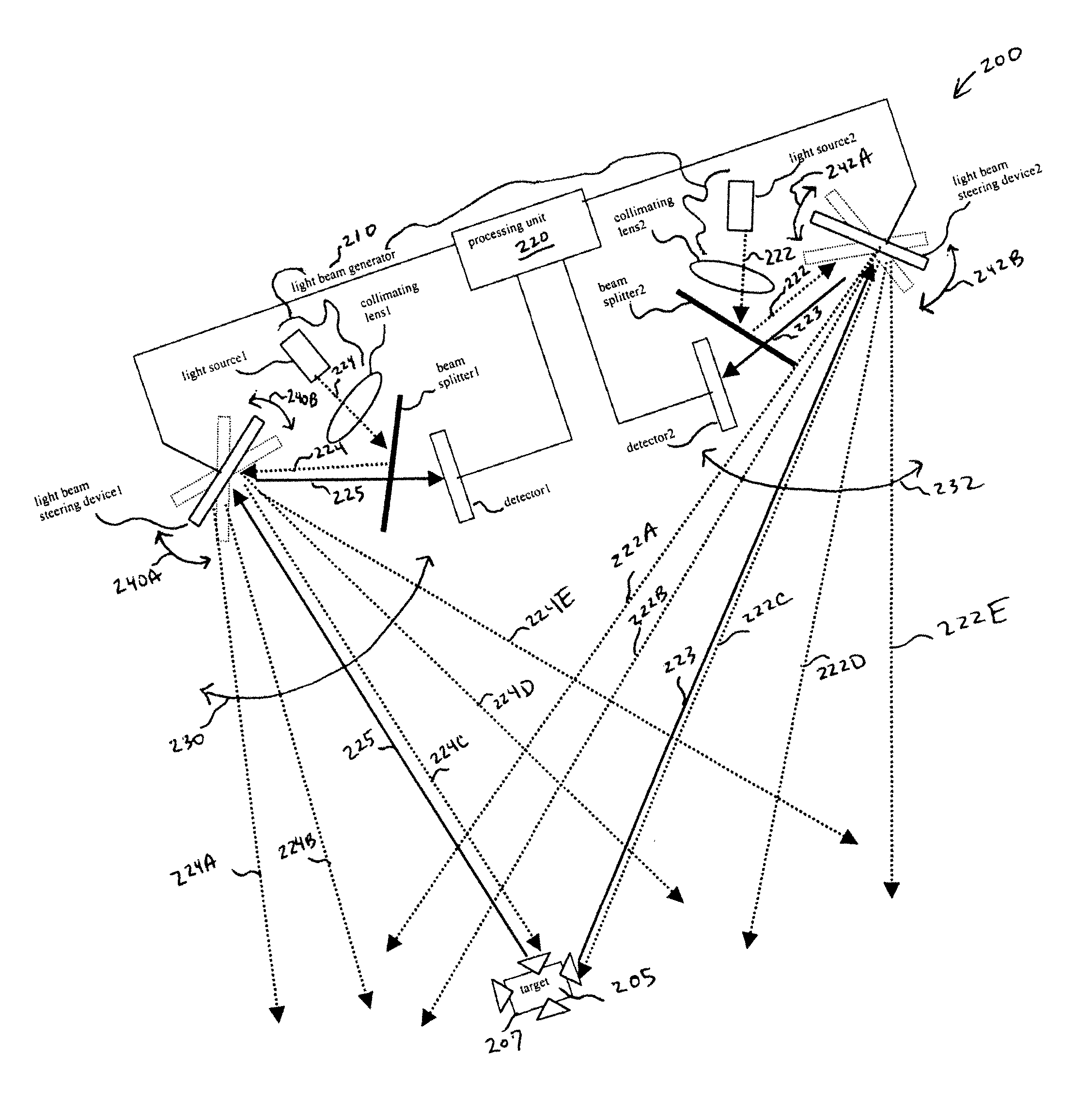
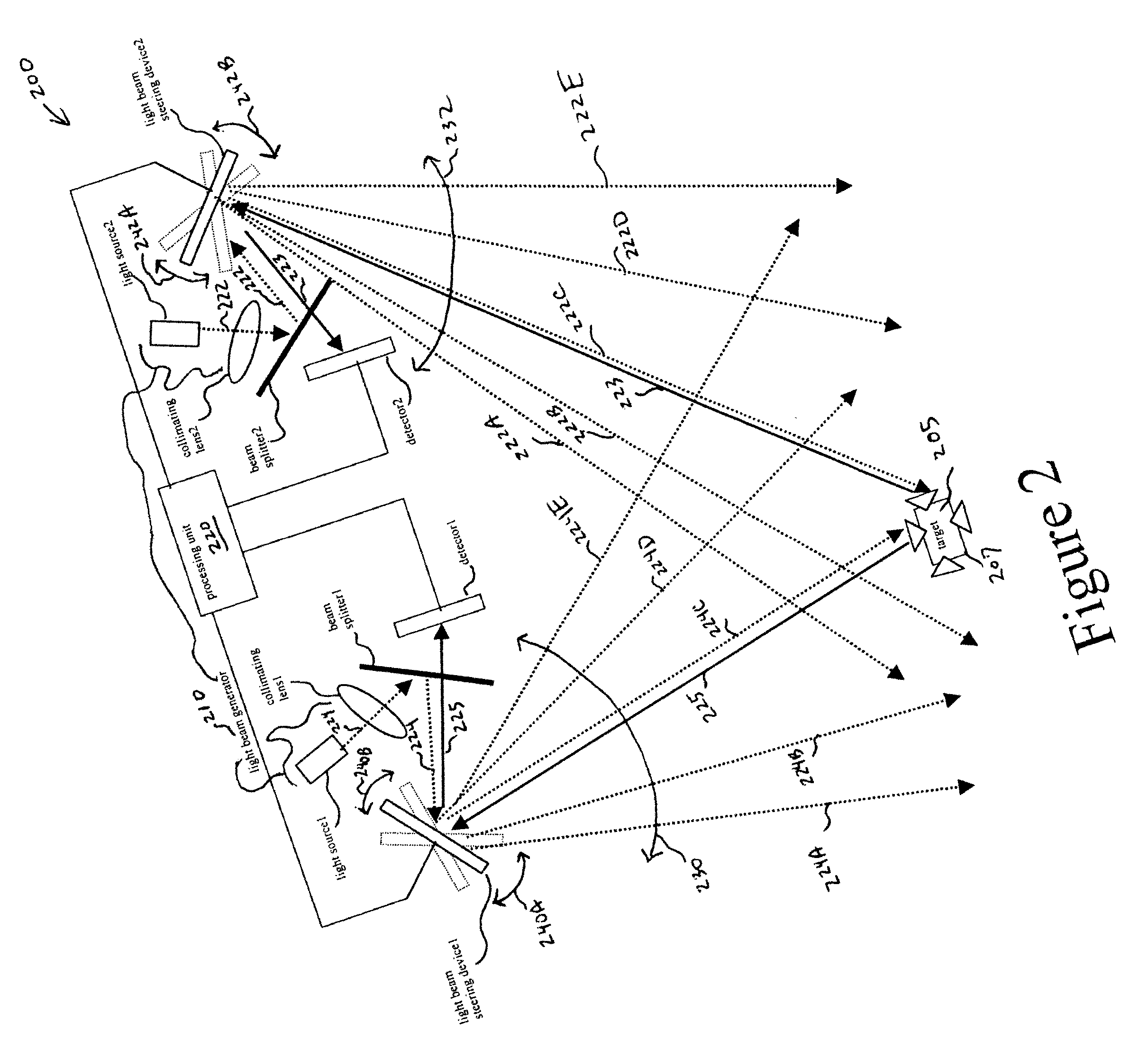
[0018] In embodiments in accordance with the invention, an optical position-tracking system comprises a light beam generator for generating a first light beam and a second light beam. Continuing, the optical position-tracking system further includes a first light bea...


PUM


Abstract

An optical position-tracking system comprises a first light beam steering device for sweeping a first light beam through a first angular range to cause a reflection of the first light beam by a target. Additionally, the optical position-tracking system further comprises a second light beam steering device for sweeping a second light beam through a second angular range to cause a reflection of the second light beam by the target. Moreover, the optical position-tracking system enables determination of a position of the target using a triangulation technique utilizing a first angular value of the first light beam and a second angular value of the second light beam. The first angular value and the second angular value depend on the existence of the respective reflection.

Description

BACKGROUND OF THE INVENTION [0001] 1. Field of the Invention [0002] The invention generally relates to optical systems. More particularly, the invention relates to optically tracking a target using a triangulation technique. [0003] 2. Related Art [0004] A variety of systems and devices have been developed to enable the input of data into a computer system and to enable the navigation / cursor control for operating the computer system. The tremendous growth in the use of computer systems can be linked to advancements in these systems and devices. [0005] These systems and devices typically utilize one of several technologies. Examples of these technologies include mechanical track-balls, acceleration detection, optical image correlation, laser speckle pattern analysis, and intensity detection. Other technologies are also used. [0006] Although improvements in these systems and devices enhance the usability of computer systems, several deficiencies in the technologies implemented by these...

Claims


Application Information

Patent Timeline
IPC IPC(8): G01B11/00G01S17/46G01S17/66G01S17/88G06F3/033G06F3/042
CPCG01S17/48G06F3/0423G01S17/88G01S17/66
Inventor XIE, TONGDEPUE, MARSHALL THOMASBANEY, DOUGLAS M.
Owner AVAGO TECH INT SALES PTE LTD
Why Eureka
Try Eureka