Spectral photometer and associated measuring head

a spectral photometer and measuring head technology, applied in the field of spectral photometers, can solve the problems of insufficient or at least insufficient general and preset profiles for all possible combinations of media and print modi, increased ambient conditions (temperature, humidity) and the danger of soiling in the vicinity of printing works

Active Publication Date: 2005-03-10
X RITE SWITZERLAND
View PDF5 Cites 38 Cited by
  • Summary
  • Abstract
  • Description
  • Claims
  • Application Information

AI Technical Summary

Problems solved by technology

Generic and preset profiles for all possible combinations of media and print modi are however not or at least not always sufficient, which is why in practice upon higher quality demands manually additional local profiles are generated and used.
However, additional limitations still exist with a built-in device with respect to the installation mass (compact shape) and possibly the we

Method used


Image

  • Spectral photometer and associated measuring head
  • Spectral photometer and associated measuring head
  • Spectral photometer and associated measuring head

Examples


Embodiment Construction

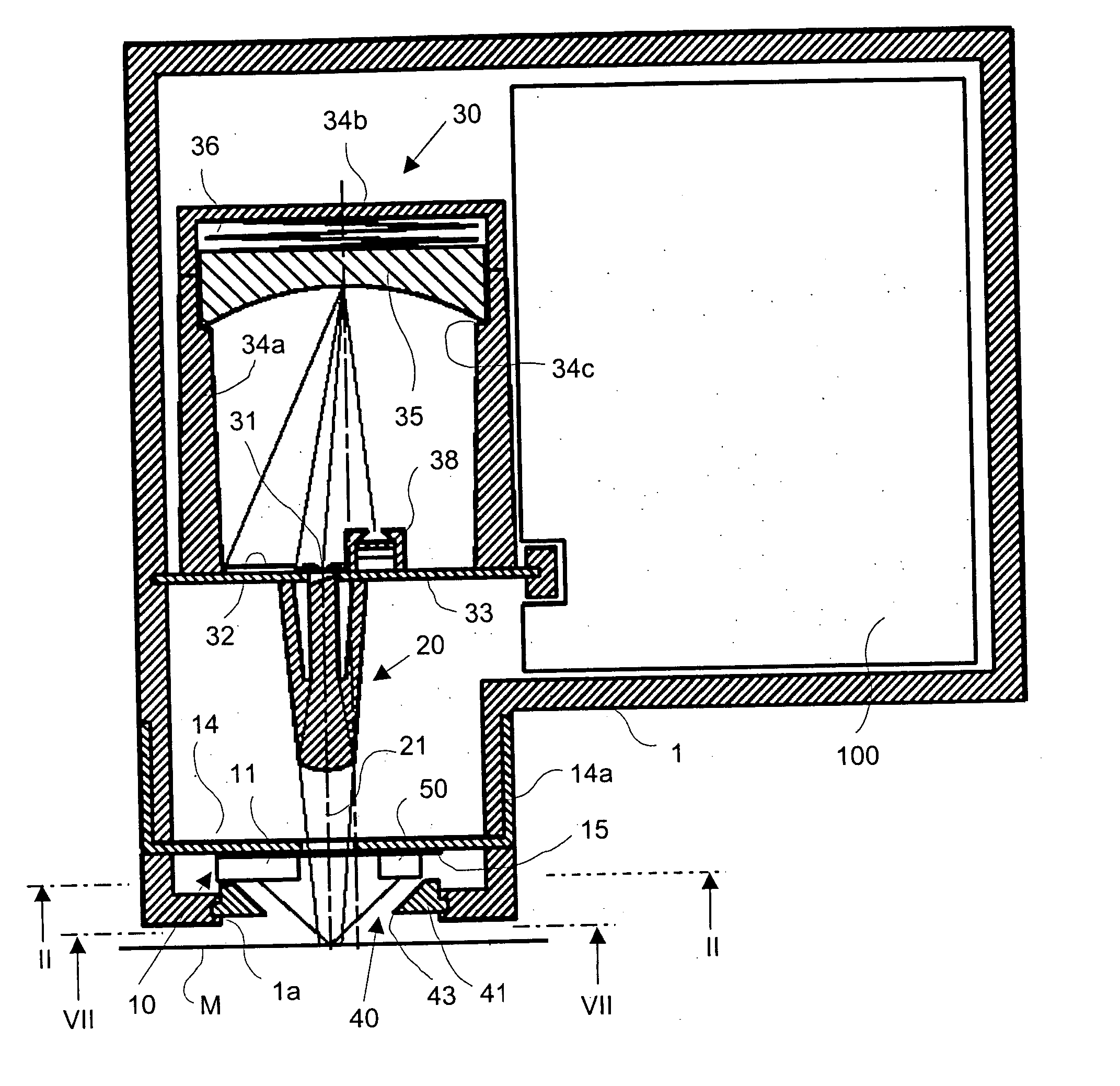
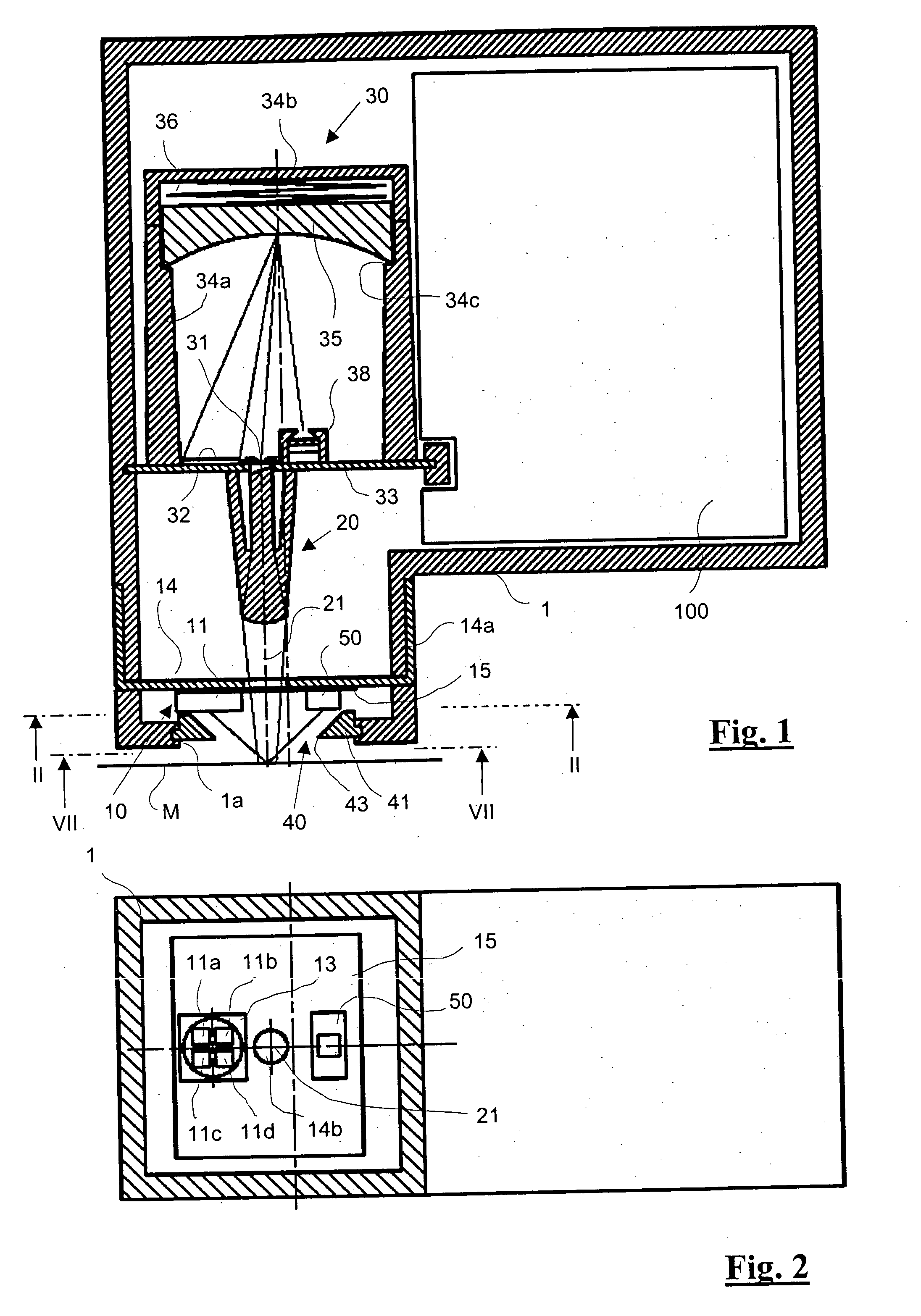
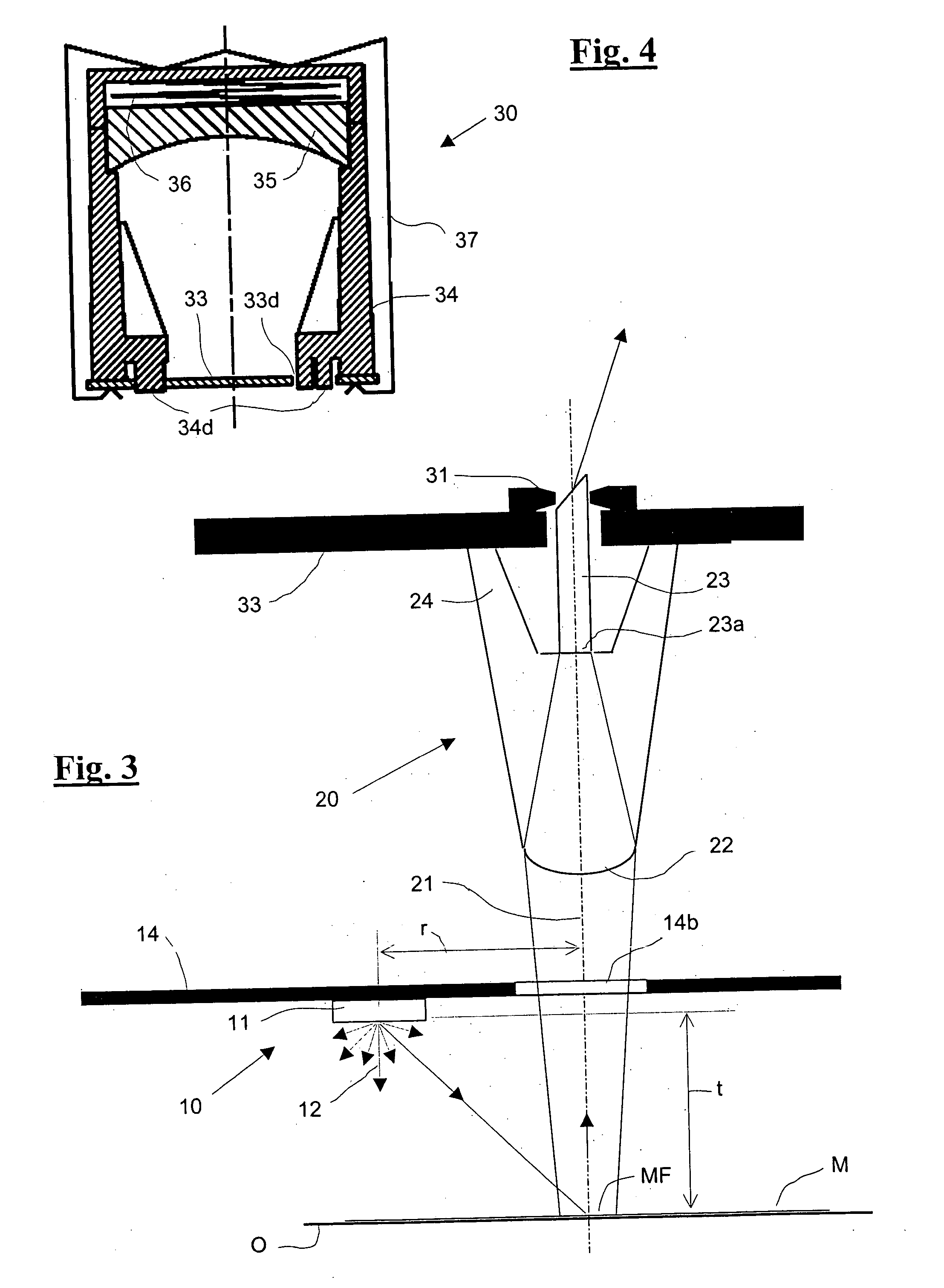
[0022] The spectral photometer includes as illustrated an outer housing 1 in which all mechanical, optical and electrical components of the spectral photometer are housed. The housing 1 has at its lower end (in the drawing) an opening 1a, through which the measurement beam path extends during operation (FIG. 1). The opening 1a is outside the operation closed by a bright reference arrangement 40 which at the same time functions as a closure (FIG. 5). The measurement plane in which a measurement object O to be measured is located in practical operation is labeled M.

[0023] The components of the spectral photometer are an illumination arrangement 10 for the illumination of the measured object O found in the measurement plane M under an angle of incidence of essentially 45°, a pickup arrangement 20 for the capture of the measurement light remitted from the measured object O at an angle of reflection of essentially 0° relative to the perpendicular of the measurement plane M, a spectromet...


PUM


Abstract

A spectral photometer intended for integration purposes includes a measurement head equipped with illumination arrangement (10) including at least one light source (11) for the illumination at an angle of incidence of 45° of a measured object and located in a measurement plane (M), a pickup arrangement (20) for capturing the measurement light remitted by the measured object at an angle of reflection of essentially 0° relative to the perpendicular to the measurement plane, a spectrometer arrangement (30) including an entry aperture (31) for the spectral splitting of the measurement light captured and fed through the entry aperture, and a photoelectric receiver arrangement (32) exposed to the split measurement light for conversion of the individual spectral components of the measurement light into corresponding electrical signals. It further includes an electronic circuit (100) for control of the light source (11) and forming digital measurement values from the electrical signals produced by the photoelectric receiver arrangement. The light source (11) is constructed as a cosign beamer and located in such a way that its main radiation direction is essentially parallel to the main beam (21) of the remitted measurement light and the mean distance of the light source from the main beam of the remitted measurement light being essentially the same as the distance of the light source (11) from the measurement plane (M). The light source (11) includes a combination of two or more light emitting diodes of different spectral characteristics located in one plane and preferably positioned on a common carrier, whereby the plane is oriented essentially parallel to the measurement plane (M). The spectrometer arrangement (30) includes a pot-shaped spectrometer housing (34) made of plastic with an essentially cylindrical mantle (34a) and a removable cover. A concave diffraction grating (35) is positioned coaxially to the mantle in the spectrometer housing and rests on an annular shoulder (34c) formed on the mantle and preferably shaped complementary to the diffraction grating. The cover (34b)forces the diffraction grating (35) against the annular shoulder (34c) at a predefined force by way of a compression spring (36). The spectrometer housing (34) is with an end opposite the cover positioned on a printed circuit plate (33) including the entry aperture (31) and the photoelectric receiver arrangement (32) and fixed to the printed circuit plate (33) by a clamping spring (37). The pickup arrangement (20) is directly mounted on that side of the printed circuit plate (33) which is opposite the side of the spectrometer housing (34).

Description

FIELD OF THE INVENTION [0001] The invention relates to a spectral photometer according to the preamble of the independent claim 1 as well as a measuring head for a spectral photometer according to the preamble of the independent claim 23. [0002] More concretely, the present invention relates to a spectral photometer intended to be built into color ready reproduction devices, especially color printers. BACKGROUND ART [0003] Color tables (so called test charts) are printed out for the characterization, ink limitation, linearization and profiling of ink jet color printers, and thereafter measured with a manual or automatic color measurement device. Spectral photometers with 45° / 0° geometry are thereby used as color measuring devices and the data used are typically L*a*b* or a spectral remissions in the range of 380 nm to 730 nm. Suitable color measurement devices are, for example, the apparatus “Spectrolino” and “i1” of the company Gretag-Macbeth AG, Regensdorf, Switzerland. [0004] Ink...

Claims


Application Information

Patent Timeline
IPC IPC(8): G01J1/06G01J3/02G01J3/10
CPCG01J1/06G01J3/02G01J3/0205G01J3/0216G01J3/524G01J3/10G01J3/501G01J3/502G01J3/0267
Inventor FRICK, BEATSCHENKEL, PAUL
Owner X RITE SWITZERLAND
Why Eureka
Try Eureka