Parallel dithering contour mitigation

a contour mitigation and parallel technology, applied in the field of digital display systems, can solve the problems of difficult to create very small intensity resolution steps, objectionable in a dim region of images, and the inability to arbitrarily small the size of lsb intensity steps

Active Publication Date: 2005-03-10
TEXAS INSTR INC
View PDF33 Cites 12 Cited by
  • Summary
  • Abstract
  • Description
  • Claims
  • Application Information

AI Technical Summary

Benefits of technology

[0017] According to another embodiment of the present invention, a display system is provided. The display system uses PWM techniques to display digital pixel data for a period proportional to the significance of a particular bit of pixel data. A group of fractional data bits are compared to threshold value provided by a three dimensional mask. The three dimensional mask represents a two dimensional array of pixels and holds threshold value that is allowed to assume one of more than two values. The result of the comparison between the fractional bits and the threshold is displayed for a period appropriate to the maximum value of the fractional bits.

Problems solved by technology

One problem encountered by PWM display systems is the difficulty in creating very small intensity resolution steps.
While a one least significant bit (LSB) intensity step is not generally objectionable when the image being displayed is very bright, it can be very objectionable in a dim region of an image.
Unfortunately, the LSB intensity step size cannot be made arbitrarily small.
Very small LSB periods are limited by the amount of data that can be loaded during the frame period or portion thereof.
Additionally, the display device itself has some finite response time.
For example, digital micromirror devices require not only a certain amount of time to load the memory array underlying the mirror array, but also a finite amount of time to reset the mirrors and allow them to transition from one position to the next.
Another problem encountered by PWM display systems is the creation of visual artifacts that arise due to the generation of an image as a series of discrete bursts of light.
PWM temporal artifacts are created when the distribution of radiant energy is not constant over an entire frame period and may be noticeable when there is motion in a scene or when the eye moves across a scene.
When viewed at a normal viewing distance, the PWM contouring artifact created by two adjacent pixels is very difficult, if not impossible, for the typical viewer to detect.
Unfortunately, bit splitting increases the necessary bandwidth of the modulator input since some of the data must be loaded into the system multiple times during a single frame period.

Method used


Image

  • Parallel dithering contour mitigation
  • Parallel dithering contour mitigation
  • Parallel dithering contour mitigation

Examples


Embodiment Construction

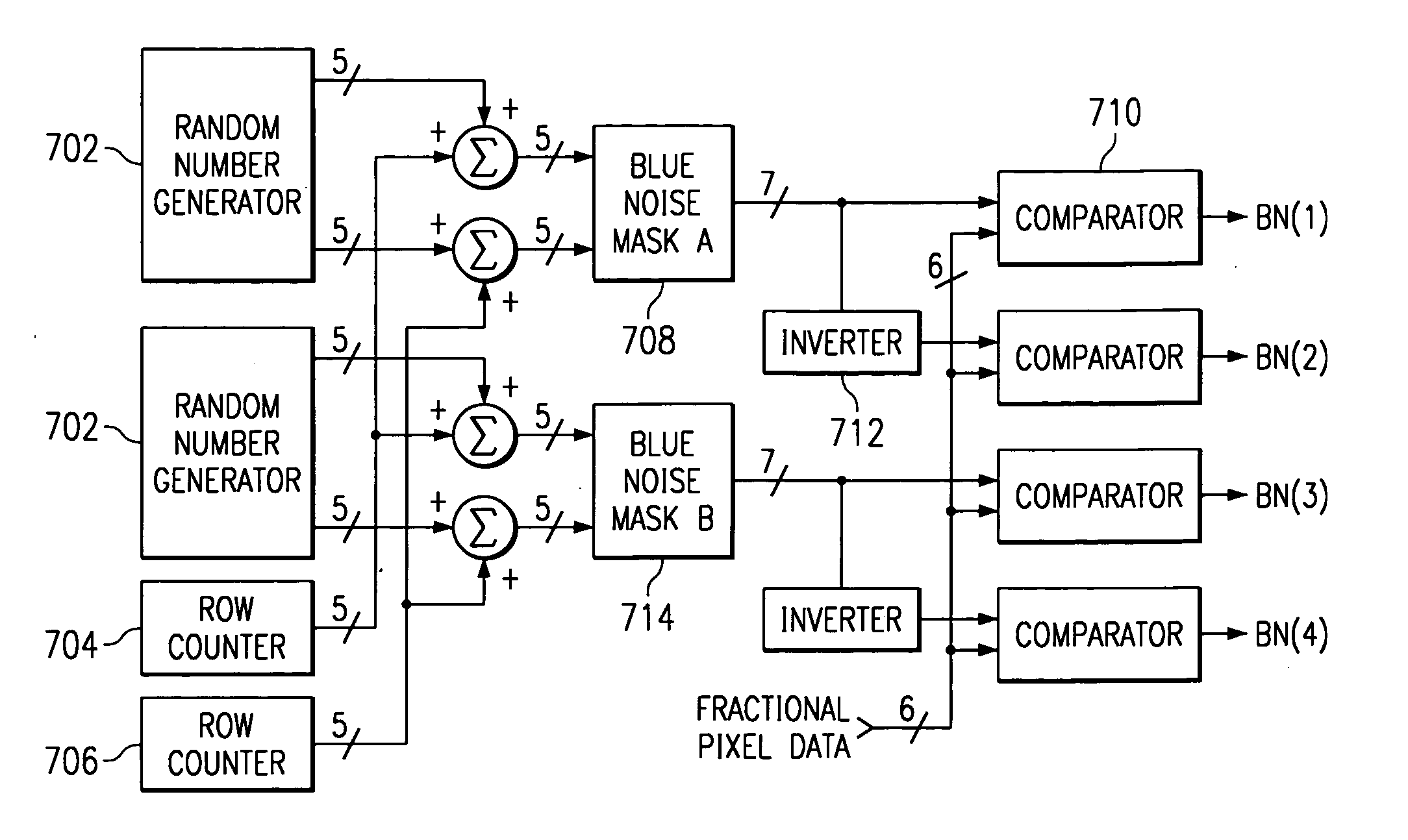
[0027] A new pulse width modulation display method has been developed that greatly reduces the PWM quantization and temporal contouring errors associated with prior PWM display systems while avoiding the extremely small bit periods that are difficult to reproduce with a micromechanical spatial light modulator such as the digital micromirror device. The new method very fine control of fractional display bits-virtually eliminating noticeable quantization contouring—without requiring very short bit display durations. The new method relies on a large multi-level mask to reduce the effective duty cycle of the fractional bits. Preferably the multi-level mask does not have a low-frequency component—clusters of ones or zeros—so that the eye is unable to detect the mask. The mask is altered, by changing the mask values and / or moving the mask relative to the image, at a rate high enough to avoid detection of the mask.

[0028] As discussed above, typical PWM display systems individually control...


PUM


Abstract

A method and system for displaying fractional bit data in order to increase the bit depth of a PWM display without requiring the use of an excessive number of bit planes. One embodiment of the present invention combines the outputs of two random number generators (702) with the outputs of a row counter (704) and column counter (706) to yield row and column indexes into two 32×32 cell blue noise masks. The row and column indexes select a blue noise mask threshold for a given pixel. The threshold from the first blue noise mask (708) is applied to a comparator (710) where it is compared to the fractional bit portion of the pixel data. A first blue noise bit, BN(1), is generated based on this comparison. Typically, BN(1) is a “1” when the fractional portion of the pixel data exceeds the threshold value from the mask. The same threshold data is also processed by inverter (712) to produce the threshold that would be shored in an inverted form of Mask A. Inverter (712) prevents the circuitry from having to store four separate blue noise masks. The output of the inverter (712) is also compared to the fractional pixel data to produce a second blue noise bit, BN(2). In the same manner, the second blue noise mask (714) is used to generate two additional blue noise bits. The four blue noise bits are then used alternately in the quad-frame display of FIG. 5 with the integer portion of the pixel data.

Description

[0001] This application claims priority from under 35 U.S.C. § 119(e)(1) of provisional application No. 60 / 184,751 filed Feb. 24, 2000. CROSS-REFERENCE TO RELATED APPLICATIONS [0002] The following patents and / or commonly assigned patent applications are hereby incorporated herein by reference: U.S. Pat. No.Filing DateIssue DateTitle5,616,228Jun. 5, 1996Apr. 8, 1997Method For ReducingTemporal Artifacts inDigital Video09 / 088,674Jun. 2, 1998Boundary Dispersion ForMitigating PWMTemporal ContouringArtifacts In DigitalDisplays09 / 572,470May 17, 2000Spoke Light Recapture InSequential Color ImagingSystems09 / 573,109May 17, 2000Mitigation Of TemporalPWM ArtifactsTI-30658HerewithBlue Noise SpatialTemporal MultiplexingFIELD OF THE INVENTION [0003] This invention relates to the field of display systems, more particularly to digital display systems using pulse width modulation. BACKGROUND OF THE INVENTION [0004] Digital display systems typically produce or modulate light as a linear function of i...

Claims


Application Information

Patent Timeline
Patent Type & Authority Applications(United States)
IPC IPC(8): G09G3/20G09G3/34
CPCG09G3/20G09G3/346G09G3/2051G09G3/2022
Inventor PETTITT, GREGORY S.WALKER, BRADLEY W.FRITZ, MATTHEW JOHN
Owner TEXAS INSTR INC
Why Eureka
Try Eureka