
Method for tapping a high voltage transmission line and substation using the same

a technology for high-voltage transmission lines and substations, which is applied in the direction of electrical equipment, emergency protective arrangements for automatic disconnection, and capacitors, etc., can solve the problems of high cost of erecting towers and running cabling, high cost of deploying a conventional substation, and low user concentration

Inactive Publication Date: 2005-03-10
GHALI GAMAL A
View PDF7 Cites 52 Cited by
  • Summary
  • Abstract
  • Description
  • Claims
  • Application Information

AI Technical Summary

Benefits of technology

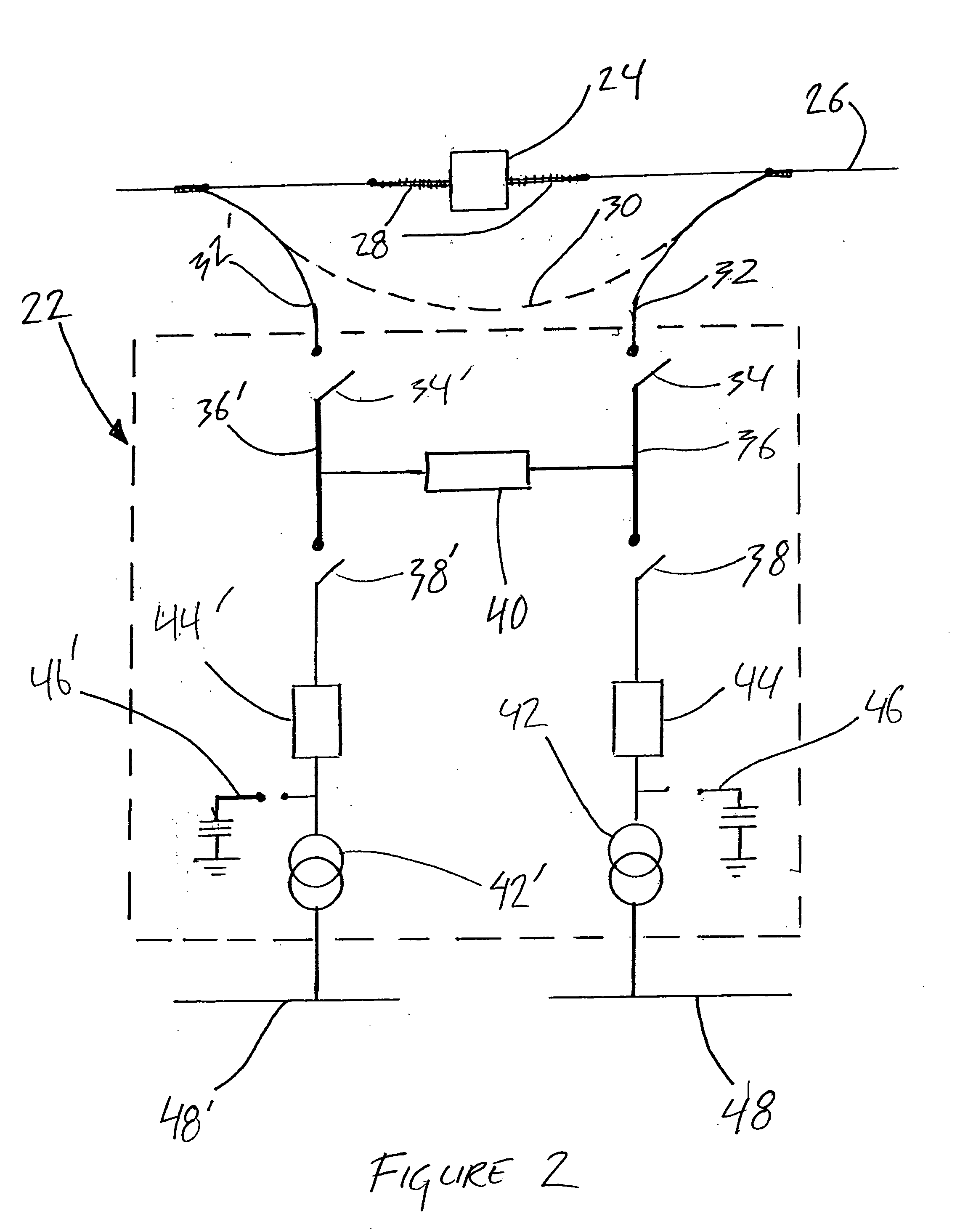
[0015] connecting the first conducting line to the primary input of the first transformer bay using a first high voltage conductor and connecting the second conducting line to the primary input of the second transformer bay using a second high voltage conductor.

Problems solved by technology

This gives rise to additional costs for erecting towers and running cabling as well as those related to the acquisition of land or grant of right of ways in order to ensure the unobstructed passage of these conductors.
In rural service areas the concentration of users is low and costs related to deploying a conventional substation are prohibitive.
As a result, in many cases a power utility will not be able to generate an adequate return on the large investment necessary to bring a conventional distribution substation on line.
On the other hand, rural users are typically satisfied with a lower quality of service and are willing to suffer some power outages if this means they will have access to electrical power at a reasonable price.
Additionally, high voltage transmission lines on their path from power source to major urban centres typically traverse many rural areas to which they do not supply electricity.
One drawback of the above non-conventional substations is that they do not provide any redundancy in the case of failure of one of the components of the substation or overload.

Method used


Image

  • Method for tapping a high voltage transmission line and substation using the same
  • Method for tapping a high voltage transmission line and substation using the same
  • Method for tapping a high voltage transmission line and substation using the same

Examples


Embodiment Construction

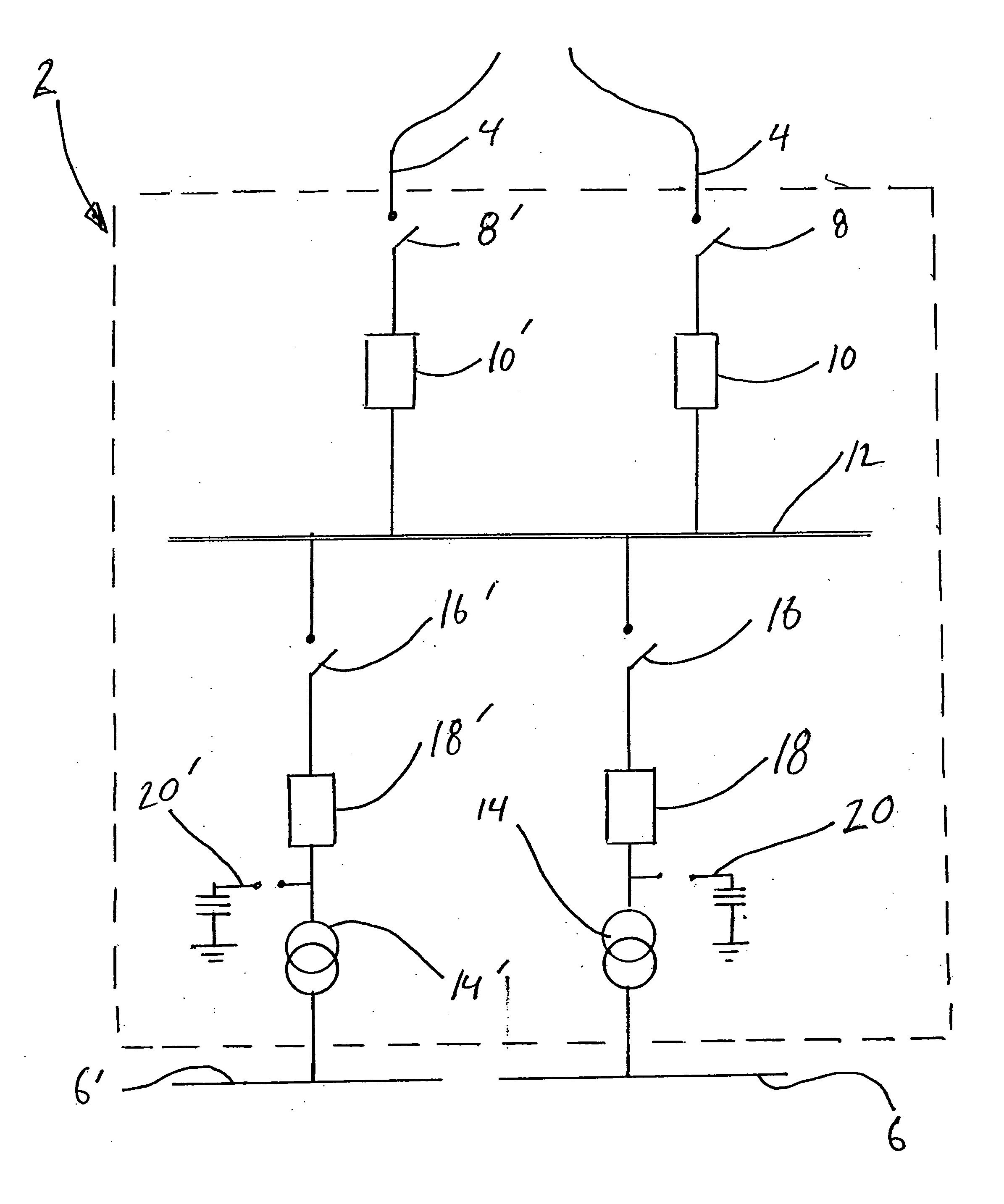
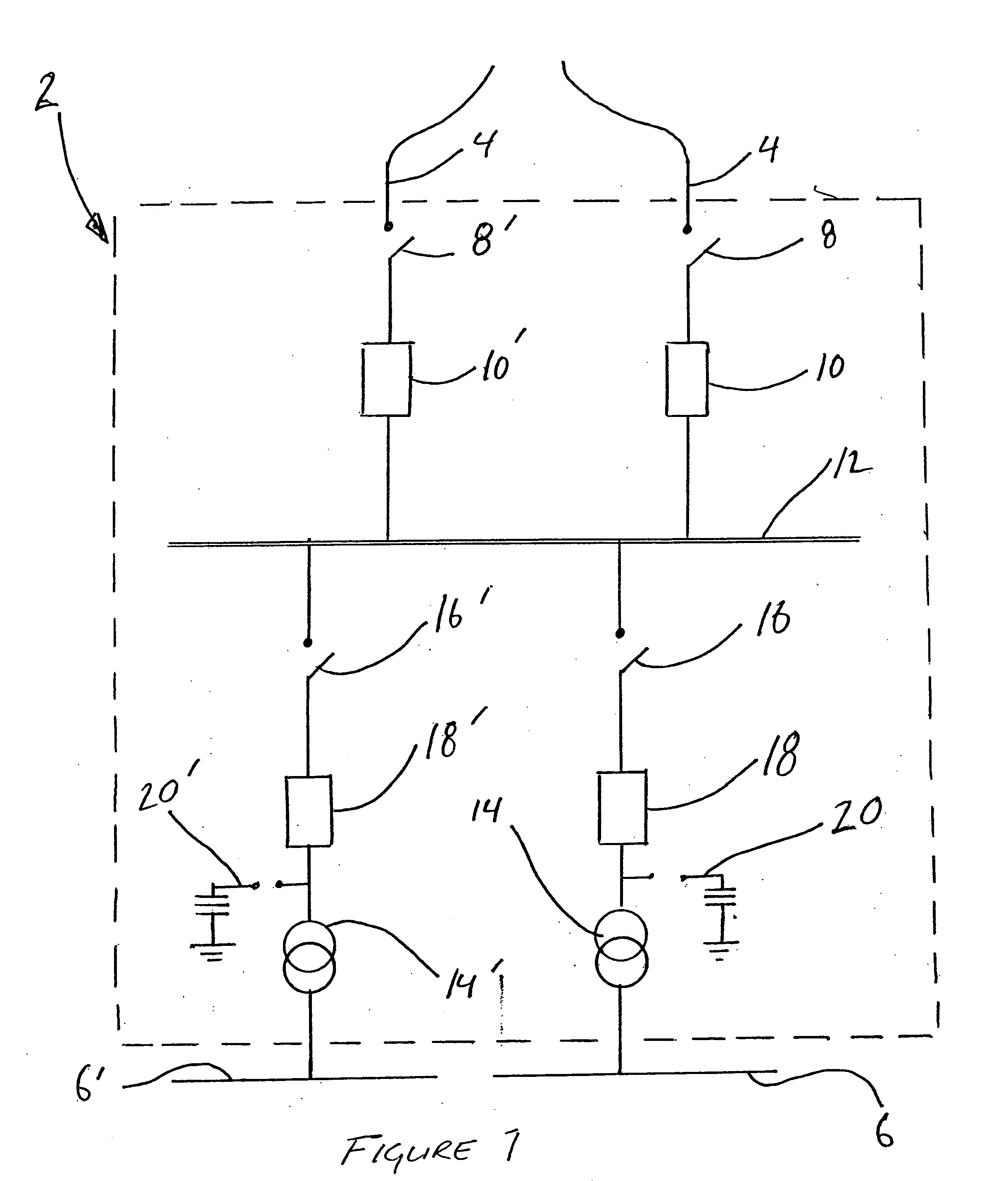
[0035] Referring now to FIG. 1, a prior art embodiment of a conventional substation is provided. In the prior art substation, generally referred to using the reference numeral 2, bulk electric power at high voltages is fed into the substation 2 by a high voltage or extra high voltage three phase AC high voltage transmission line 4 (having a voltage of typically between 69 kV and 765 kV). The high voltage or extra high voltage is reduced by the substation 2 to a voltage which is suitable for distribution via one or more power lines as in 6, typically at a voltage of between 4 kV and 46 kV, depending on implementation. The power lines 6 can, for example, serve as the primary feeders of a utility's distribution grid. It will be apparent to a person of ordinary skill in the art that although only a single conductor is shown, in a three phase embodiment a multiple of three conductors is required per transmission path.

[0036] Within the substation 2, the high voltage transmission line 4 i...


PUM


Abstract

A method of tapping a high voltage transmission line for input into a power distribution substation and system for the conversion of the tapped high voltage electricity to medium voltage electricity are disclosed. The method comprises the steps of dividing the transmission line and attaching the conductors to the primaries of at least two transformers via a series connected first disconnect switch, second disconnect switch and circuit breaker. A bus interconnects the first disconnect switch and the second disconnect switch and the bus of the first transformer bay is connected to the bus of the second transformer bay using a circuit breaker. The system comprises an insulator dividing the transmission line into separate conducting lines and attaching them to the primaries of at least two transformers via a series connected first disconnect switch, second disconnect switch and circuit breaker. A bus interconnects the first disconnect switch and the second disconnect switch and the bus of the first transformer bay is connected to the bus of the second transformer bay using a circuit breaker. The secondaries of said power transformer output the medium voltage electricity.

Description

FIELD OF THE INVENTION [0001] The present invention relates to a method for tapping a high voltage transmission line by a substation. In particular, the present invention relates to a non-conventional substation which can tap directly into a high voltage transmission line in order to step down the voltage to connect to a distribution grid or a large industrial, commercial or institutional user. BACKGROUND OF THE INVENTION [0002] Electrical distribution systems are an essential part of the electrical power system. In order to transfer power from the place of generation to the place of use, some type of transmission network must be utilised. A large transmission system, of the type designed to transfer large amounts of energy to a large number of users, involves a system of interconnected power transmission lines originating at the electrical power generating stations (or power plants), which are typically dispersed over a wide area, with the ultimate purpose of the transmission lines...

Claims


Application Information

Patent Timeline
Patent Type & Authority Applications(United States)
IPC IPC(8): H02B5/00H02H3/05H02H7/055
CPCH02B5/00H02H7/055H02H3/05
Inventor GHALI, GAMAL A.
Owner GHALI GAMAL A
Learn More