Method of determining an optimal control profile for adjusting tray-in/out speeds of an optical disk drive

a technology of optical disk drive and control profile, which is applied in the direction of digital signal error detection/correction, instruments, recording signal processing, etc., can solve the problem of optical disk dropping out of position with excessive for

Inactive Publication Date: 2005-03-10
LITE ON IT
View PDF9 Cites 7 Cited by
  • Summary
  • Abstract
  • Description
  • Claims
  • Application Information

AI Technical Summary

Benefits of technology

[0014] (d) determining an optimal control profile according to the comparison values of step (c).

Problems solved by technology

However, considering the cost of production, the prior art optical disk drive includes merely a limit switch instead of close-loop sensors for detecting whether the tray arrives at its end-stop.
In mass production, owing to: (1) different tray-in / out forces due to variations in disk clampers, (2) inconsistency of devices with different friction forces, and (3) different ways of oil filling with different brake forces, an unique and constant control profile is not suitable for all optical disk drives.
Furthermore, improper tray-in / out speeds can cause the tray to be incapable of driving all the way to its end-stop, or to accelerate rapidly, causing an optical disk to be out of position (i.e. dropped out from the tray) with excessive force.

Method used


Image

  • Method of determining an optimal control profile for adjusting tray-in/out speeds of an optical disk drive
  • Method of determining an optimal control profile for adjusting tray-in/out speeds of an optical disk drive
  • Method of determining an optimal control profile for adjusting tray-in/out speeds of an optical disk drive

Examples


Embodiment Construction

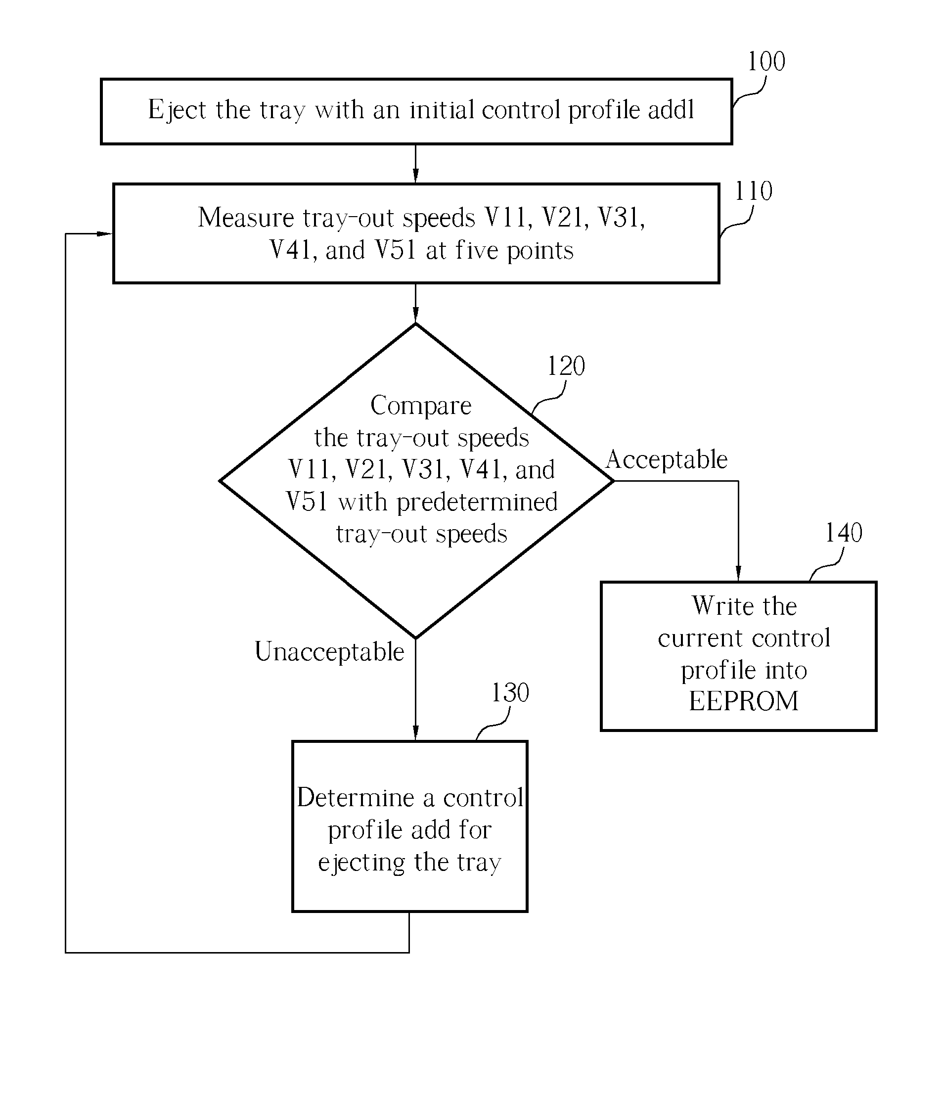
[0019] In first embodiment, a plurality of control profile sets for tray-in / out speeds of a tray in an optical disk drive are established, and an optimal control profile of the tray is thus selected by aid of pre-established sensors.

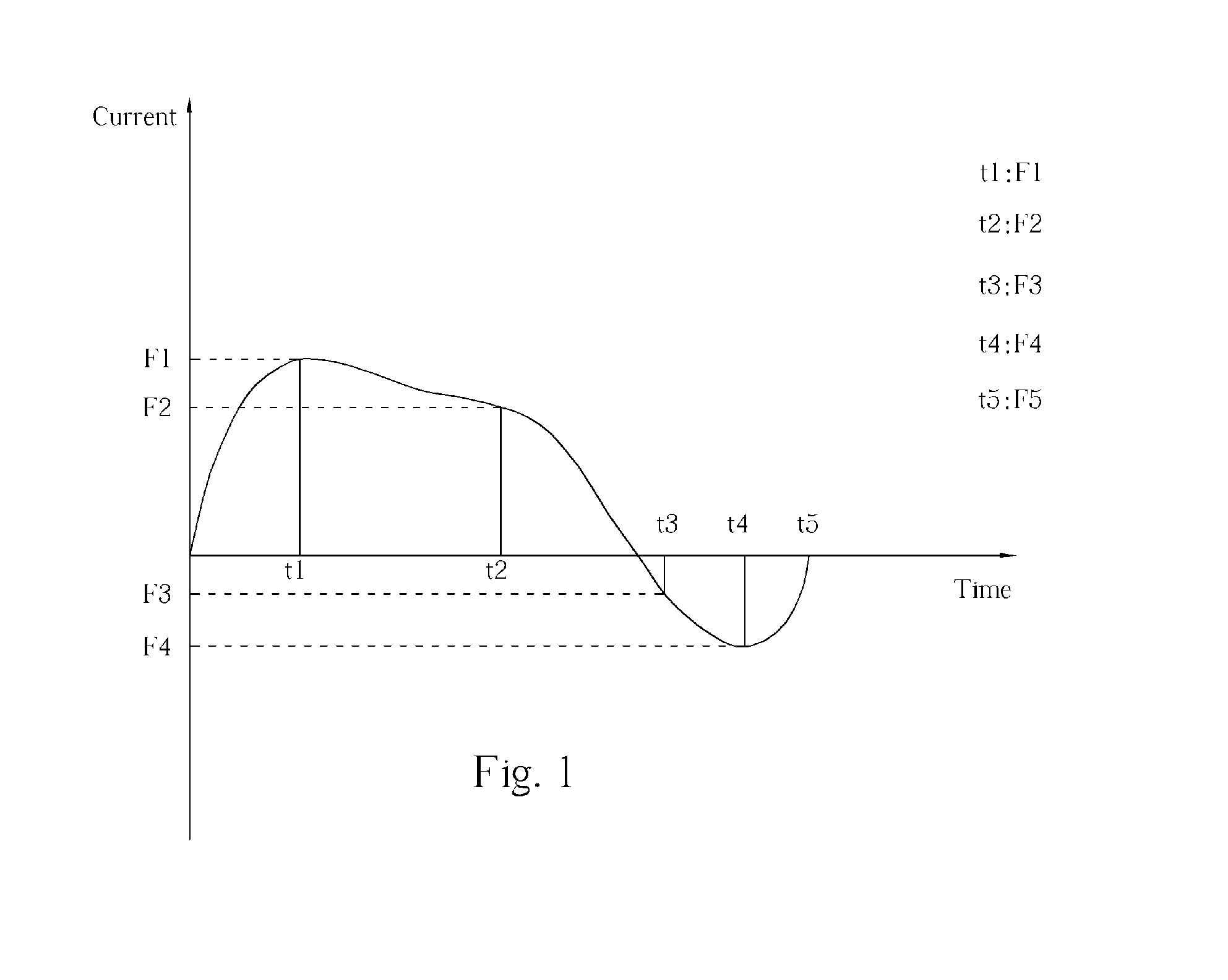
[0020] Please refer to FIG. 1, which illustrates a control profile graph of drive current for the tray versus time. If the control profile is applied to drive the tray for movement (drive tray-out for example), ejection force is provided by a positive drive current before time point t3. After time point t3, the tray has almost reached its end-stop, so a brake force is provided by a negative current to stop the tray as it approaches the end-stop.

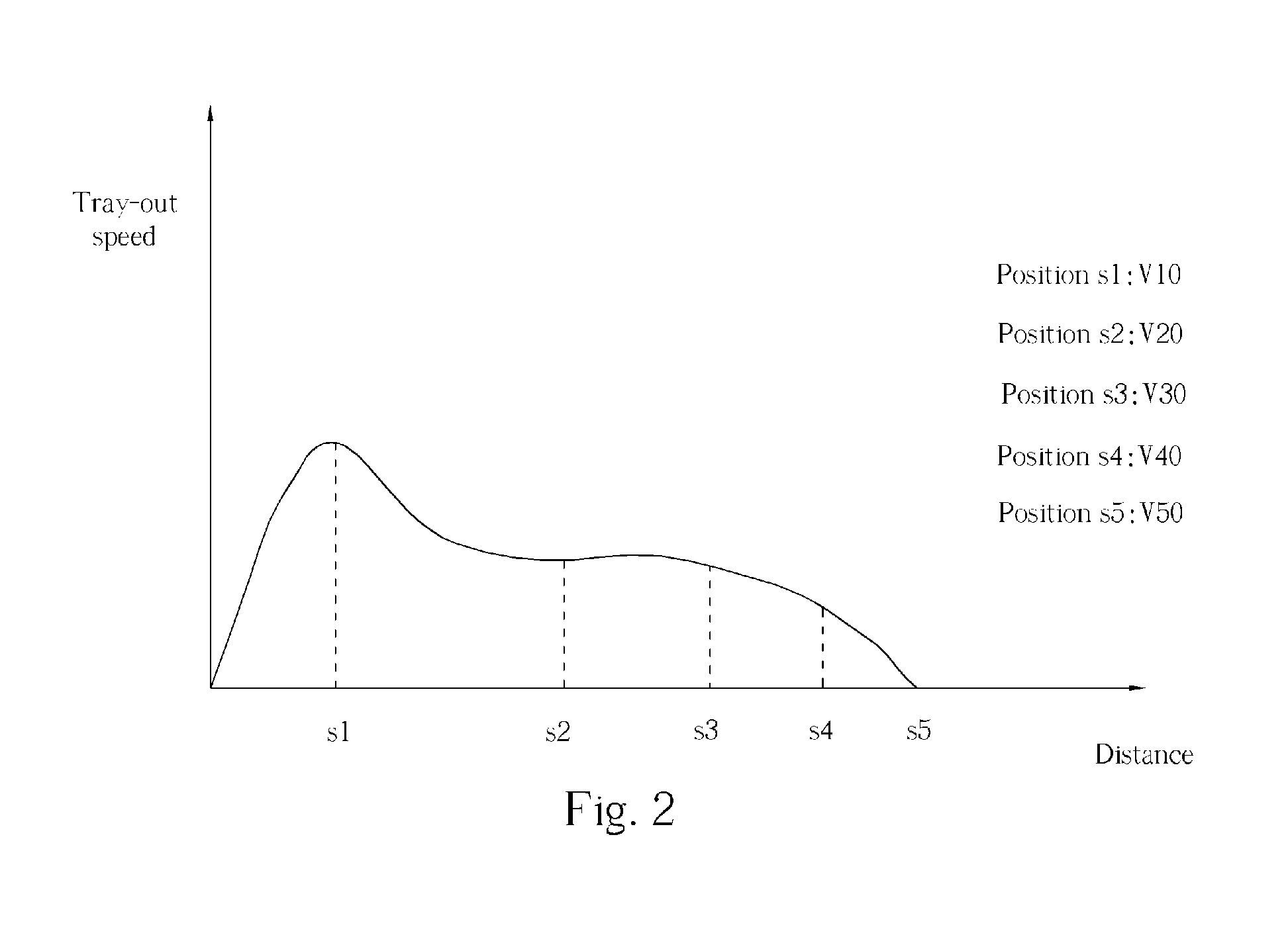
[0021] Please refer to FIG. 2, which illustrates a graph of tray-out speeds versus the tray-out distance of the tray. The optical disk drive divides the tray-out distance into five segments with five points in addition to the origin, s1, s2, s3, s4, and s5, a sensor is set up in each point for determining tray-o...


PUM

PropertyMeasurementUnit
speedsaaaaaaaaaa
tray speedsaaaaaaaaaa
movement distanceaaaaaaaaaa

Abstract

The present invention discloses an adjusting method applicable to tray-in and tray-out speeds in optical disk drives. Firstly, a number of control profiles are set up, a tray-out operation of is executed by an initial control profile, and the tray speed measured by means of sensors. If the tray speed is not acceptable, then an optimal control profile is selected from the preset control profiles according to the unacceptable tray speed.

Description

BACKGROUND OF INVENTION [0001] 1. Field of the Invention [0002] The present invention provides a method for adjusting tray-in / out speeds of a tray, and more particularly, a method of determining an optimal control profile for adjusting tray-in / out speeds of a tray in an optical disk drive. [0003] 2. Description of the Prior Art [0004] Tray-in / out speeds of a tray in a prior art optical disk drive are constant. The prior art optical disk drive controls the tray-in / out speeds with a direct-current motor by means of an open-loop-control method. The open-loop-control method includes operations of constant voltage / current, constant control profile, etc. [0005] The open-loop-control method is to provide tray-in / out forces for the tray according to operations of the optical disk drive. [0006] However, considering the cost of production, the prior art optical disk drive includes merely a limit switch instead of close-loop sensors for detecting whether the tray arrives at its end-stop. [0007...

Claims


Application Information

Patent Timeline
Patent Type & Authority Applications(United States)
IPC IPC(8): G11B7/085G11B15/675G11B17/04
CPCG11B17/056
Inventor CHANG, SUNG-SAN
Owner LITE ON IT
Why Eureka
Try Eureka