Digitally controlled voltage regulator

a voltage regulator and digital control technology, applied in the direction of electric variable regulation, process and machine control, instruments, etc., can solve the problems of large drooping and overshooting of the regulated output voltage, requiring increasingly capable power supplies, and conventional single-stage buck converters, which are not suitable for many applications, and can not provide adequate power for many applications

Active Publication Date: 2004-08-05
INFINEON TECH AUSTRIA AG
View PDF6 Cites 79 Cited by
  • Summary
  • Abstract
  • Description
  • Claims
  • Application Information

AI Technical Summary

Problems solved by technology

As electronic components become increasingly powerful, fast and complex, such devices require increasingly capable power supplies.
Conventional single-stage buck converters, however, typically do not provide adequate power for many applications due to thermal constraints and efficiency requirements.
Dynamic microprocessor current requirements are roughly 250 A / uSec, resulting in substantial "droop" and "overshoot" of the regulated output voltage.
The slew limitations of the power stage, due to the output filter inductance, must be supplemented by microprocessor decoupling capacitors.
Due to size and cost restraints, it is not desirable to utilize large quantities of high quality capacitors.
Moreover, the use of analog signaling is inferior since it is more susceptible to differential noise pickup which may degrade signal accuracy or precision.

Method used


Image

  • Digitally controlled voltage regulator
  • Digitally controlled voltage regulator
  • Digitally controlled voltage regulator

Examples


Embodiment Construction

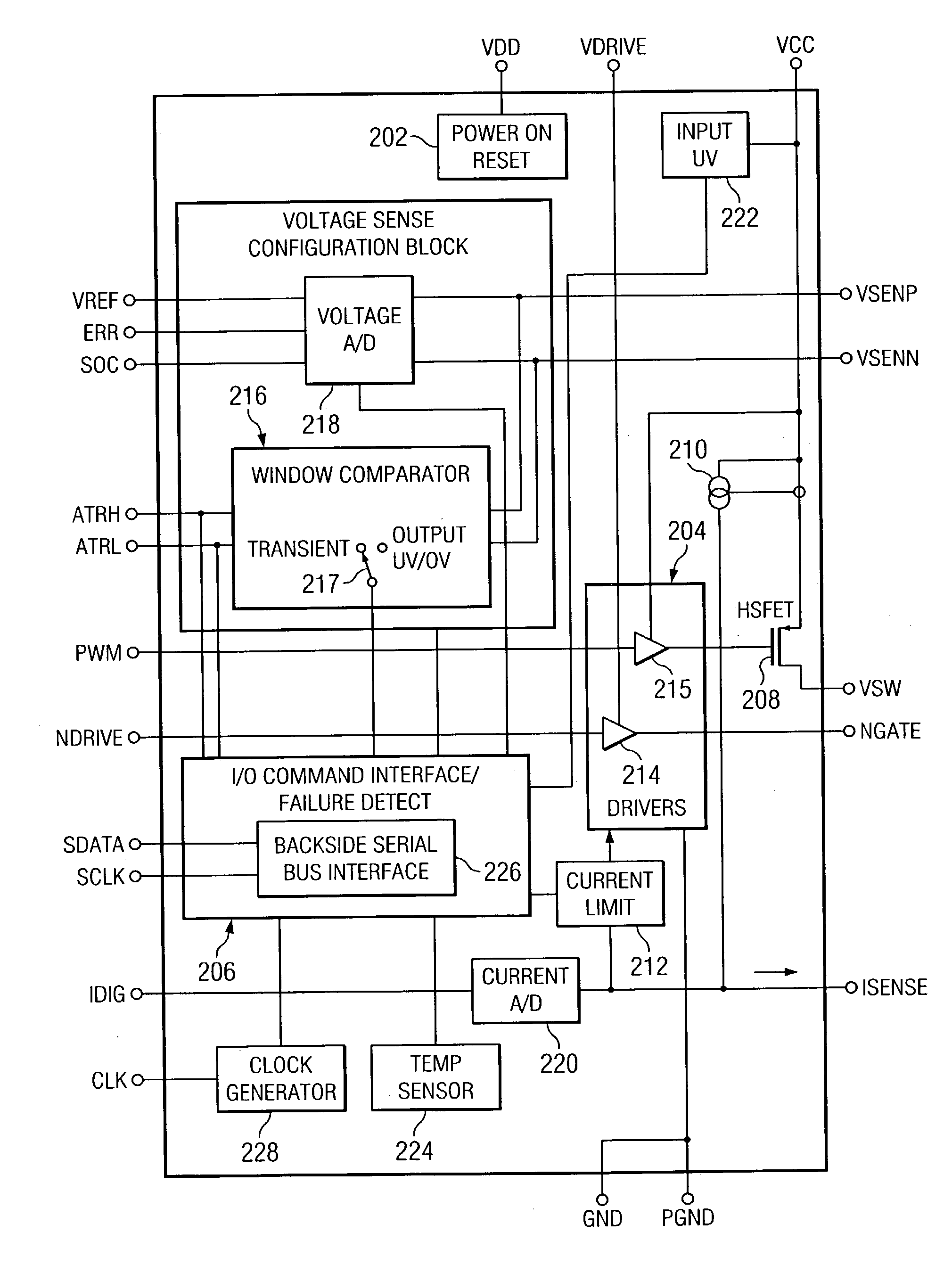
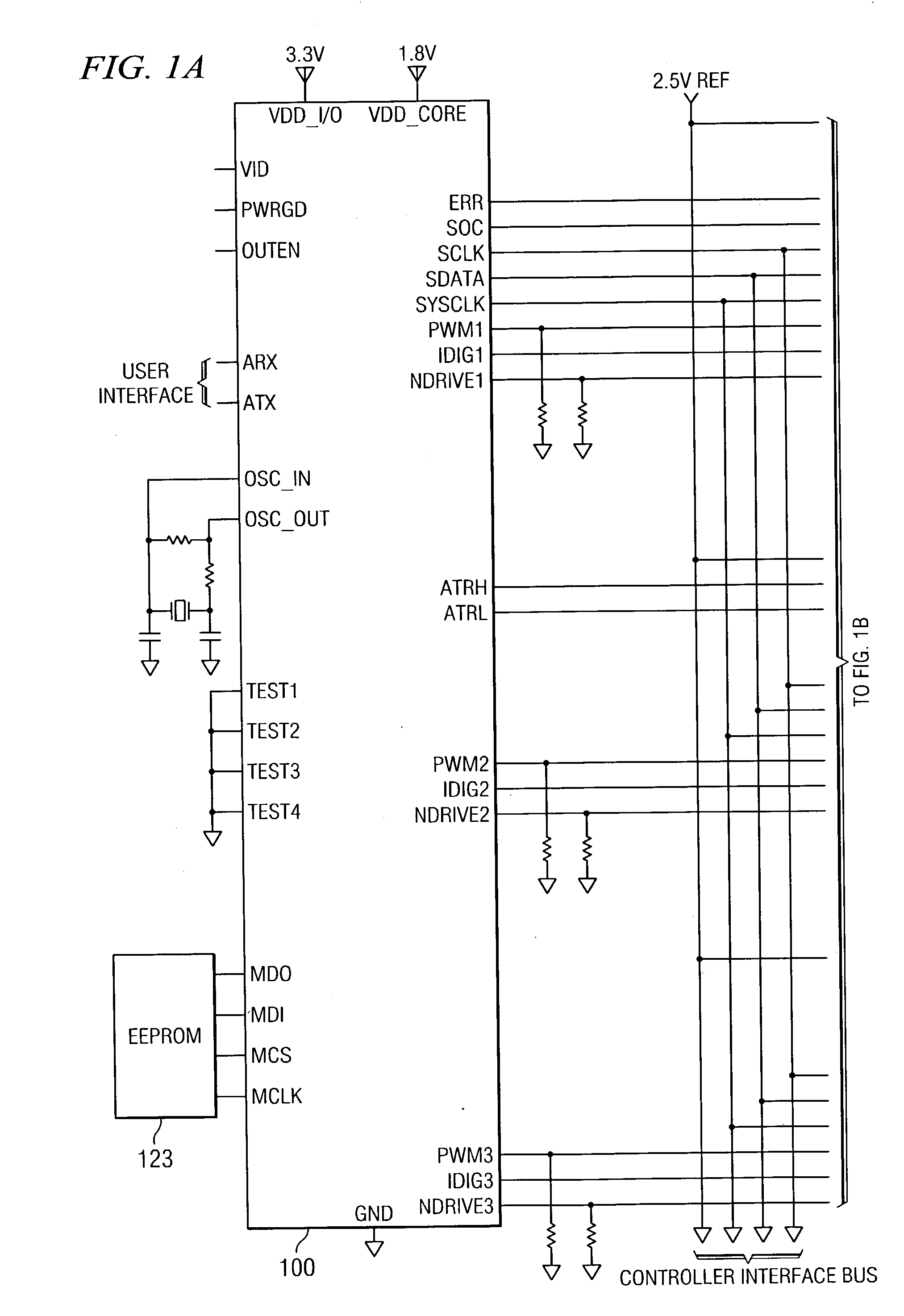
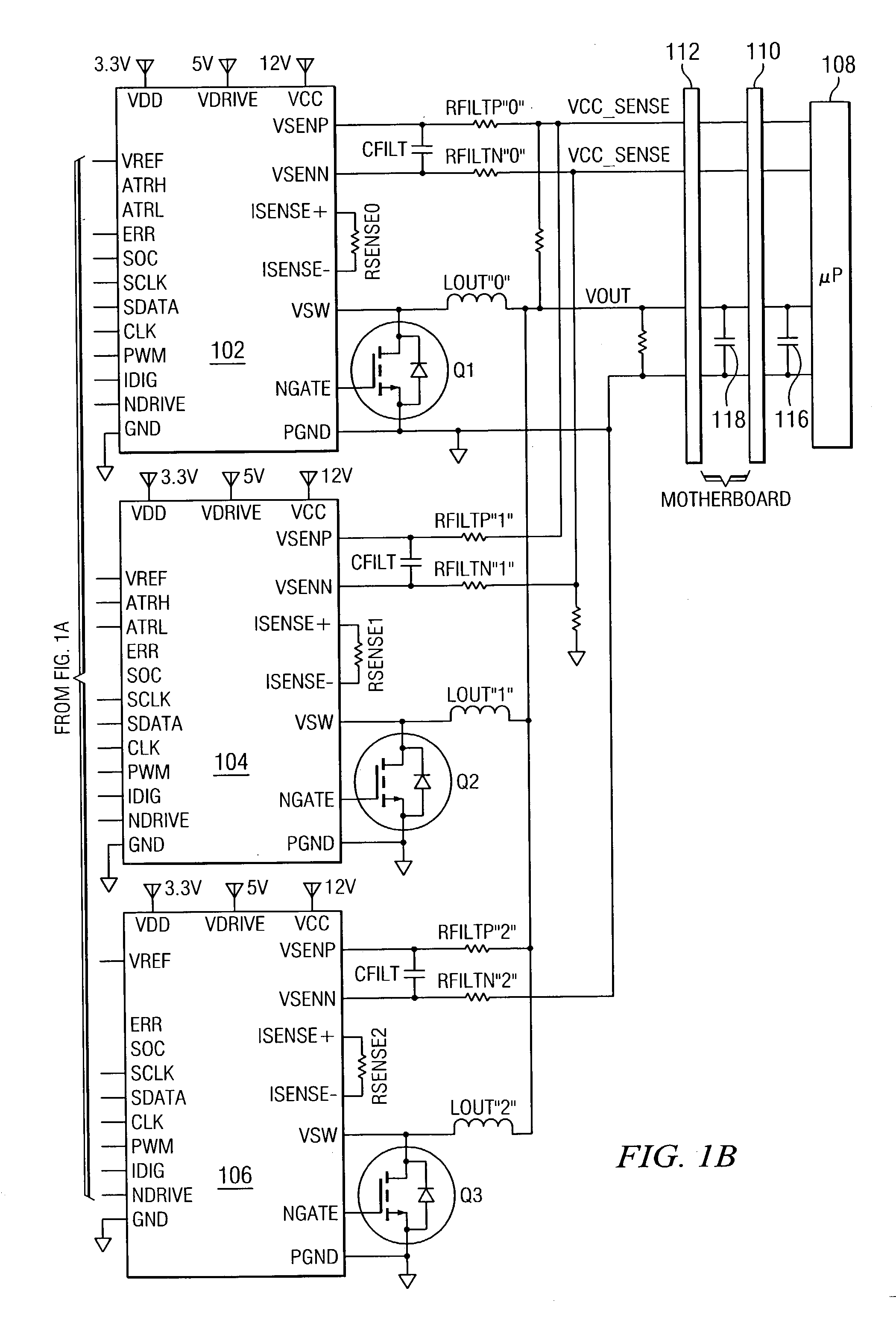
[0028] In accordance with the exemplary embodiment of the invention, a voltage regulator implemented in a multi-chip system that utilizes digital control to deliver clean power to microprocessor loads is shown in FIGS. 1A and 1B (collectively FIG. 1). The digital controlled voltage regulator comprises a single digital control IC 100 coupled to a plurality of power IC's 102, 104, and 106. Although the illustrated example shows three power IC channels, the illustrated system utilizes six channels. The illustrated Controller Interface Bus connects to three additional power IC's similar to 102, 104 and 106 and not specifically shown in the drawing figure to simplify the description. Those skilled in the art will recognize that the number of channels is a matter of design choice and any number of channels could be utilized. The power IC's 102, 104, and 106 are connected in parallel and provide multiple phases of load current to the processor 108 with a precisely controlled output voltage...


PUM


Abstract

Disclosed is a digitally controlled multi-phase voltage regulator system providing regulated power to electronic components that have variable power requirements. Power is supplied by one or more power integrated circuits (IC) each having a high side power switch controlled by pulse width modulated signals and a low side power switch. The power IC senses voltage at the load and has an on-chip current mirror for generating a current that is a ratio of current delivered to the load. The power IC also has current limiting and on-chip temperature sensing components. The voltage and current information is digitized and provided to a control integrated circuit (IC). The control IC receives this digitized information as well as user provided parameters and, in the regulation mode of operation, provides digitized pulse width modulated control signals to the power IC. In an active transient response mode of operation, the control IC provides signals to turn either the high side switches or low side switches ON. Fault detection circuitry identifies over voltage, under voltage, and excessive temperatures. All communications between the control IC and the power IC are digital providing high bandwidth, optimal control frequency response, noise immunity and efficient active transient response.

Description

CROSS-REFERENCES TO RELATED PATENT APPLICATIONS[0001] 1. U.S. patent application Ser. No. 10 / 237,903, filed on Sep. 9, 2002, by Trivedi et al, entitled: SYSTEM & METHOD FOR CURRENT HANDLING IN A DIGITALLY-CONTROLLED POWER CONVERTER.[0002] 2. U.S. patent application Ser. No. is pending; filed on Nov. 12, 2002, by Duffy et al, entitled: "METHODS AND APPARATUS FOR REDUCING PARASITIC INDUCTANCE USING INTER-DIGITATED BOND WIRES",[0003] 3. U.S. patent application Ser. No. 9 / 978,296, filed on Oct. 15, 2001, by Goodfellow et al, entitled: "SYSTEM AND METHOD FOR CURRENT SENSING".[0004] 1. Technical Field[0005] The present invention relates generally, to voltage regulators and, more particularly, to a digitally controlled multi-phase voltage regulator system to provide power to electronic components, such as microprocessors and the like.[0006] 2. Background Information[0007] Electronic components, such as microprocessors require fast, intelligent power systems, typically referred to as voltag...

Claims


Application Information

Patent Timeline
Patent Type & Authority Applications(United States)
IPC IPC(8): H02M3/157H02M3/158
CPCH02M3/157Y02B70/1466H02M3/1588H02M3/1584Y02B70/10
Inventor GOODFELLOW, JOHN RYANCARROLL, ROBERT T.TRIVEDI, MALAYMCSHANE, ERIKMORI, KEVIN
Owner INFINEON TECH AUSTRIA AG
Why Eureka
Try Eureka