Reflection suppression for an optical fiber

a technology of optical fibers and suppression devices, applied in the field of optical fibers, can solve problems such as performance problems, interference with network performance, and performance problems, and achieve the effects of suppressing back reflections, suppressing internal reflections, and suppressing reflections

Active Publication Date: 2005-03-10
ARRIS SOLUTIONS
View PDF68 Cites 36 Cited by
  • Summary
  • Abstract
  • Description
  • Claims
  • Application Information

AI Technical Summary

Benefits of technology

[0105] One skilled in the art would appreciate that the present invention supports managing back reflections in optical fiber systems such as optical networks. In one embodiment, the present invention suppresses internal reflections from an exposed end face of an optical fiber that is optically active but is held in reserve for future service. Forming a coil of controlled radius adjacent an exposed end face of an optical fiber suppresses back reflections from that end face. The radius of the coil is small enough to impair the optical fiber's ability to maintain a waveguided state and large enough to control mechanical stress in the optical fib

Problems solved by technology

If the intensity of the optical signal that is incident upon the optical detector is higher than its dynamic range, the optical detector's performance can suffer.
This reflected light can then back propagate in the optical fiber and can interfere with network performance.
Such stray light reflections from openly terminated optical fibers in an optical network can cause performance problems.
Specifically, stray reflections from openly terminated optical fibers can impair the performance of an optical communications link by interfering with an optical detector, for example.
That is, when an optical network concurrently transmits a reflected optical signal and an optical signal supporting desired communication information to an optical detector, the signal-to-noise ratio of the network can suffer.
Stray reflections can also impair the performance of a semiconductor laser.
When light reflects off an end face of an optical fiber and back into a semiconductor laser, the back reflected light can interference with the laser's operation.
For example, the back reflected light can destabilize the laser's lasing cavity.
Isolators are often coupled to high performance lasers and generally are considered too expensive for routine fiber optic applications.
Implementing these approaches

Method used


Image

  • Reflection suppression for an optical fiber
  • Reflection suppression for an optical fiber
  • Reflection suppression for an optical fiber

Examples


Embodiment Construction

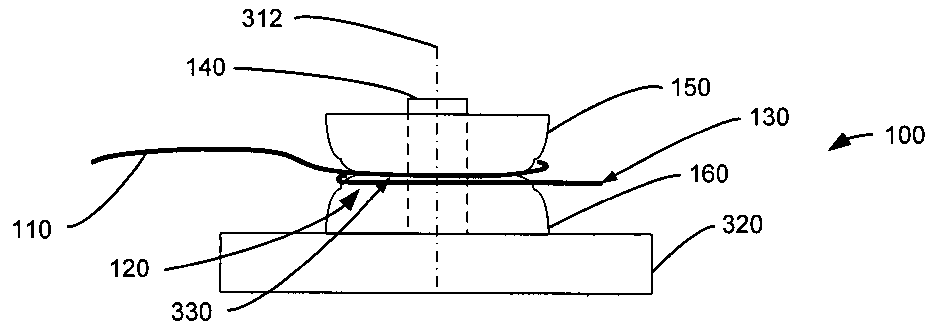
[0037] Exemplary embodiments of the present invention support managing reflections in optical systems, such as suppressing internal reflections from an end face of an optical fiber. A termination attenuation spool attenuates light propagating forward in an optical fiber towards an exposed end face, and then attenuates the light internally reflected by the end face that back propagates in the optical fiber. Turning now to the drawings, in which like numerals indicate like elements throughout the several figures, preferred and exemplary embodiments of the invention will be described in detail.

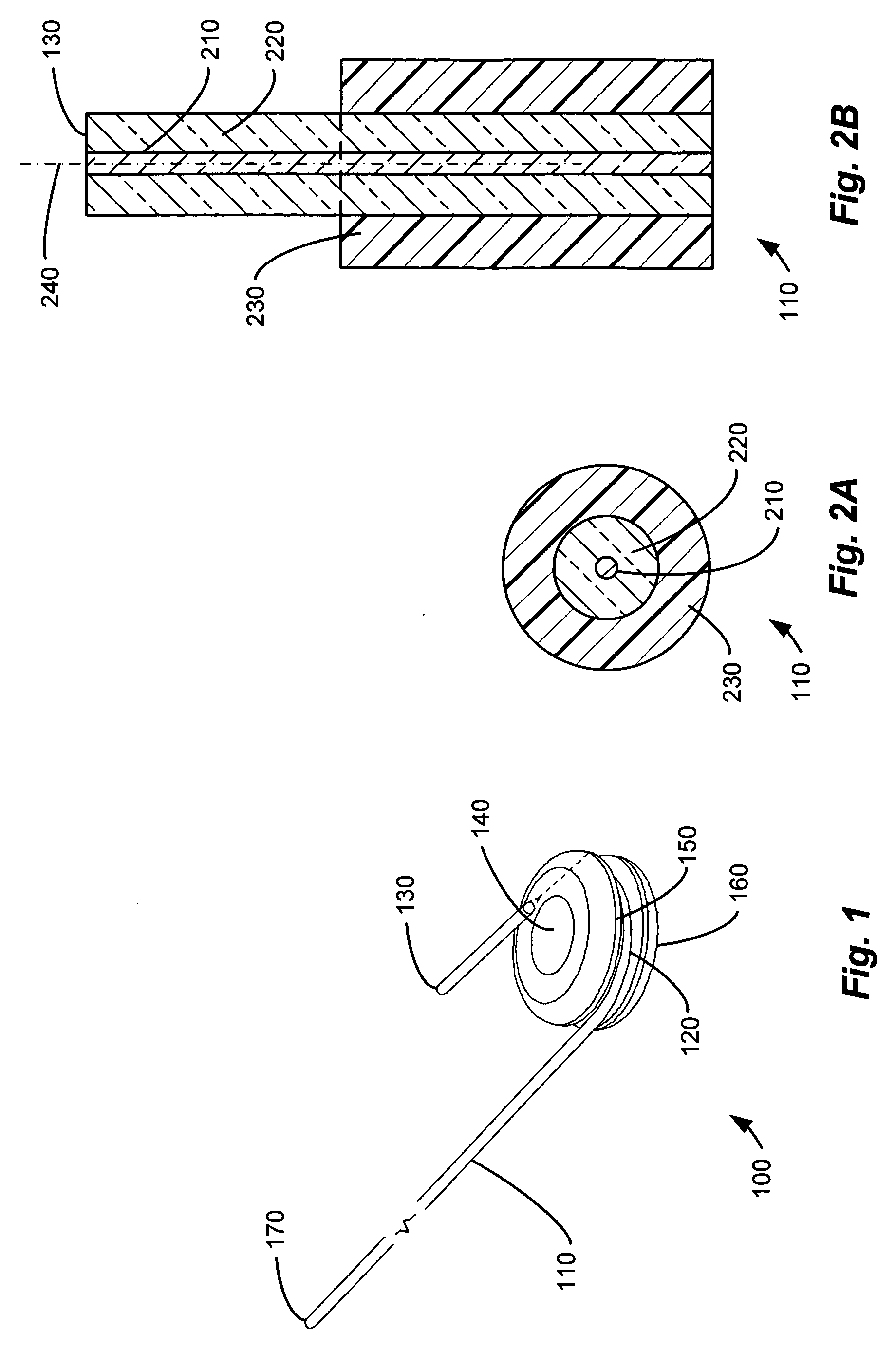
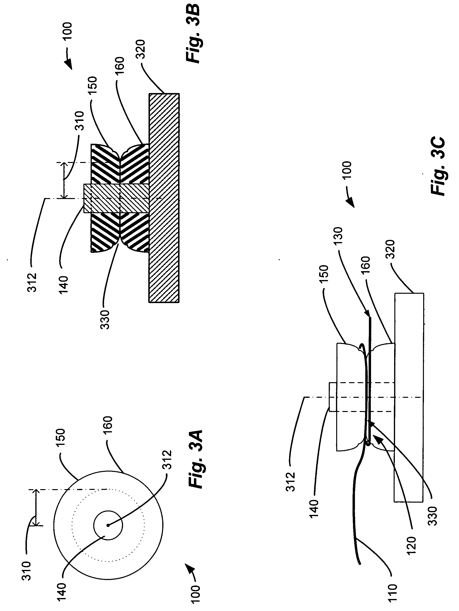
[0038]FIG. 1 illustrates a perspective view of an optical fiber 110 coiled around a termination attenuation spool 100. One end face 130 of the optical fiber 110 is exposed to the surrounding environment, which is typically a gaseous medium such as air. The termination attenuation spool 100 includes a top section 150 and a bottom section 160. A cylindrical rod 140 joins the top section 150 and th...


PUM


Abstract

Forming a plurality of loops in an optical fiber around a spool adjacent to an exposed end face can suppress internal reflections from the exposed end face. The radius of the loops can attenuate light that is propagating to and from the end face by causing light to leak out of the optical fiber's core and into its cladding. The radius can be selected to control physical stress in the optical fiber and promote reliability. The radius and the number of loops can be selected to meet a return loss specification. The loops can be formed by coiling the optical fiber around a spool that includes a slot for holding the optical fiber until it is put into service.

Description

CROSS REFERENCE TO RELATED APPLICATIONS [0001] This application claims the benefit of priority to U.S. Provisional Application Ser. No. 60 / 418,271 entitled “Method of Providing Low Cost Termination of an Unused Fiber Optic Strand” filed Oct. 15, 2002. The subject matter of U.S. Provisional Application Ser. No. 60 / 418,271 is hereby fully incorporated herein by reference. [0002] This application is related to U.S. Non-Provisional application Ser. No. 10 / 045,439, entitled “Cable Splice Enclosure and Components,” filed Nov. 7, 2001. The subject matter of U.S. Non-Provisional application Ser. No. 10 / 045,439 is hereby fully incorporated herein by reference.FIELD OF THE INVENTION [0003] The present invention relates to optical fibers and more particularly to managing internally reflected light in fiber optic terminations. BACKGROUND OF THE INVENTION [0004] Optical fiber is useful in communication networks to transmit digital and analog information via modulated optical signals. In a typica...

Claims


Application Information

Patent Timeline
IPC IPC(8): G02B6/26G02B6/44
CPCG02B6/4457G02B6/266
Inventor HODGE, RONALD L.KENNY, JOHN J.
Owner ARRIS SOLUTIONS
Why Eureka
Try Eureka