
Developing cartridge, photosensitive member cartridge, process unit, and image forming apparatus

a technology of developing cartridges and photosensitive drums, which is applied in the direction of electrographic process apparatus, instruments, optics, etc., can solve the problems of unstable distance between the developing roller and the photosensitive drum, and the inability to achieve reliable separation

Active Publication Date: 2005-03-10
BROTHER KOGYO KK
View PDF7 Cites 73 Cited by
  • Summary
  • Abstract
  • Description
  • Claims
  • Application Information

AI Technical Summary

Benefits of technology

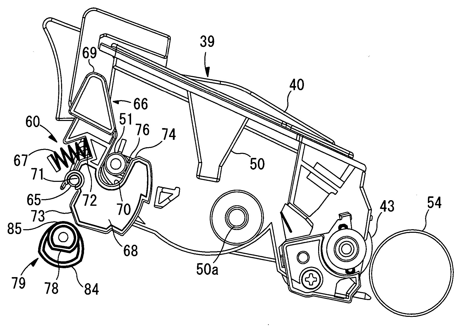
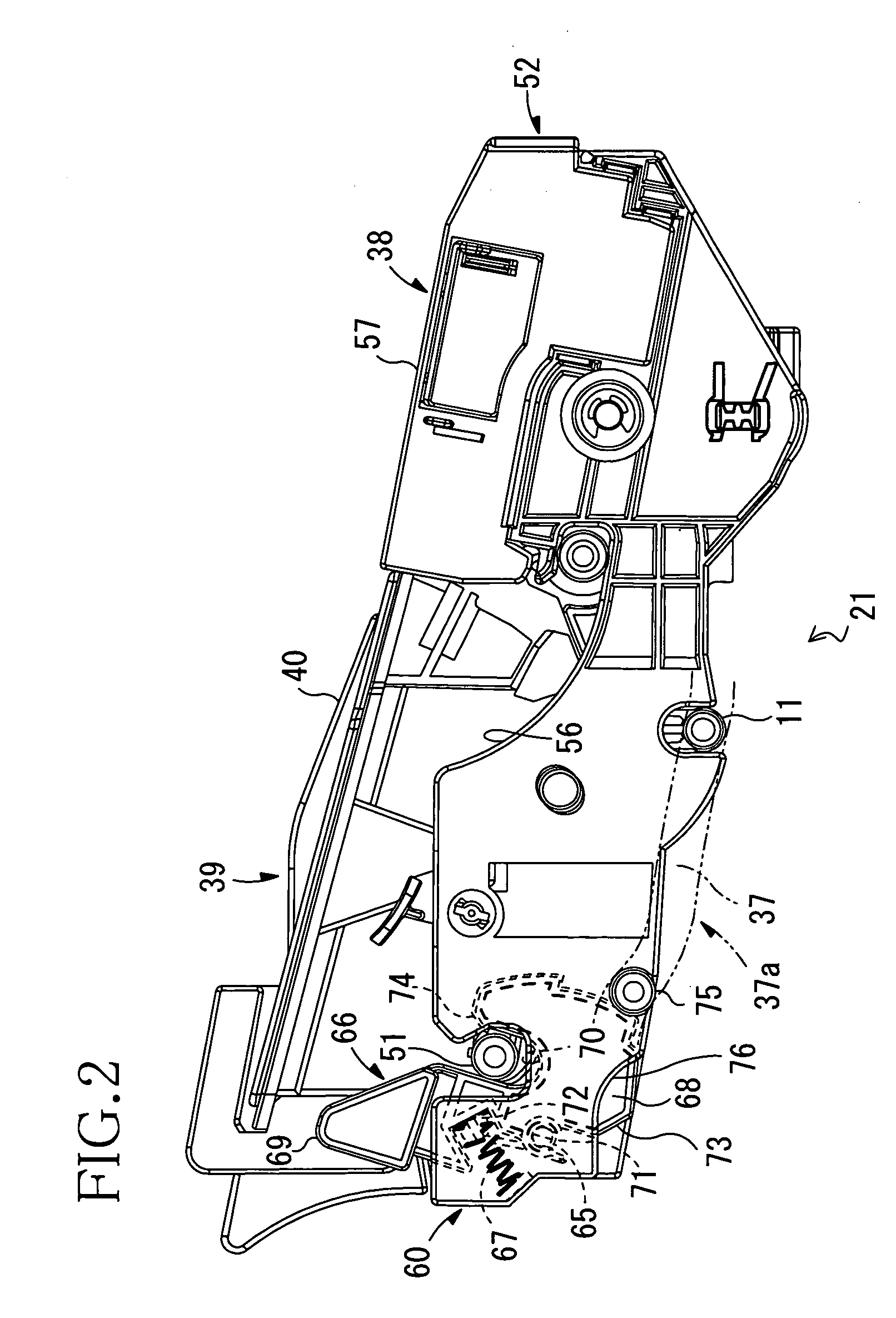
[0010] With such a structure, when the lever provided in the frame of the photosensitive member cartridge is in engagement with the developing cartridge, the lever moves between the contact position and the separation position, thereby the developing agent carrier and the photosensitive member are brought into contact with or separated from each other. Thus, this prevents the developing agent carrier from moving along with the photosensitive member cartridge. As a result, the developing agent carrier can be stably separated from the photosensitive member, and a reliable separation can be achieved.
[0012] With such a structure, the engaging portion of the developing cartridge engages the lever, and the lever moves between the contact position and the separation position, thereby the developing agent carrier and the photosensitive member are brought into contact with or separated from each other. This prevents the developing agent carrier from moving along with the photosensitive member cartridge. As a result, the developing agent carrier can be stably separated from the photosensitive member and a reliable separation can be achieved.
[0014] With such a structure, when the engaging portion of the developing cartridge is received in the receiving portion of the lever, the lever moves between the contact position and the separation position, thereby the developing agent carrier and the photosensitive member are brought into contact with or separated from each other. This prevents the developing agent carrier from moving along with the photosensitive member cartridge. As a result, the developing agent carrier can be stably separated from the photosensitive member and a reliable separation can be achieved.
[0016] With such a structure, when the lever provided in the frame of the photosensitive member cartridge is in engagement with the developing cartridge, the lever moves between the contact position and the separation position, whereby the developing agent carrier and the photosensitive member are brought into contact with or separated from each other. This prevents the developing agent carrier from moving along with the photosensitive member cartridge. As a result, the developing agent carrier can be stably separated from the photosensitive member, whereby a reliable separation can be achieved.
[0018] The invention provides, among other things, an image forming apparatus that enables contact or separation between a developing agent carrier and a photosensitive member and smooth attaching and detaching of a process unit with respect to an accommodating portion.
[0020] With such a structure, the lever is moved between the contact position and the separation position due to an engagement between the moving member and the lever, whereby the photosensitive member and the developing agent carrier can make contact with or separate from each other. When the cover is moved from the closed position to the open position to remove the process unit from the accommodating portion, the engagement releasing member releases the engagement between the lever and the moving member with the move of the cover. Thus, while the developing cartridge and the photosensitive member can make contact with or separate from each other, when the process unit is removed from the accommodating portion, even if the lever engages the moving member, the engagement therebetween can be released with the move of the cover from the closed position to the open position, and a smooth attaching and detaching of the process unit with respect to the accommodating portion can be achieved.

Problems solved by technology

However, if the separation mechanism is provided in the main body case, when the developing roller makes contact with or is separated from the photosensitive drum, the drum cartridge is apt to move integrally with the developing unit, a distance between the developing roller and the photosensitive drum would become unstable, thereby a reliable separation can not be achieved.

Method used


Image

  • Developing cartridge, photosensitive member cartridge, process unit, and image forming apparatus
  • Developing cartridge, photosensitive member cartridge, process unit, and image forming apparatus
  • Developing cartridge, photosensitive member cartridge, process unit, and image forming apparatus

Examples


Embodiment Construction

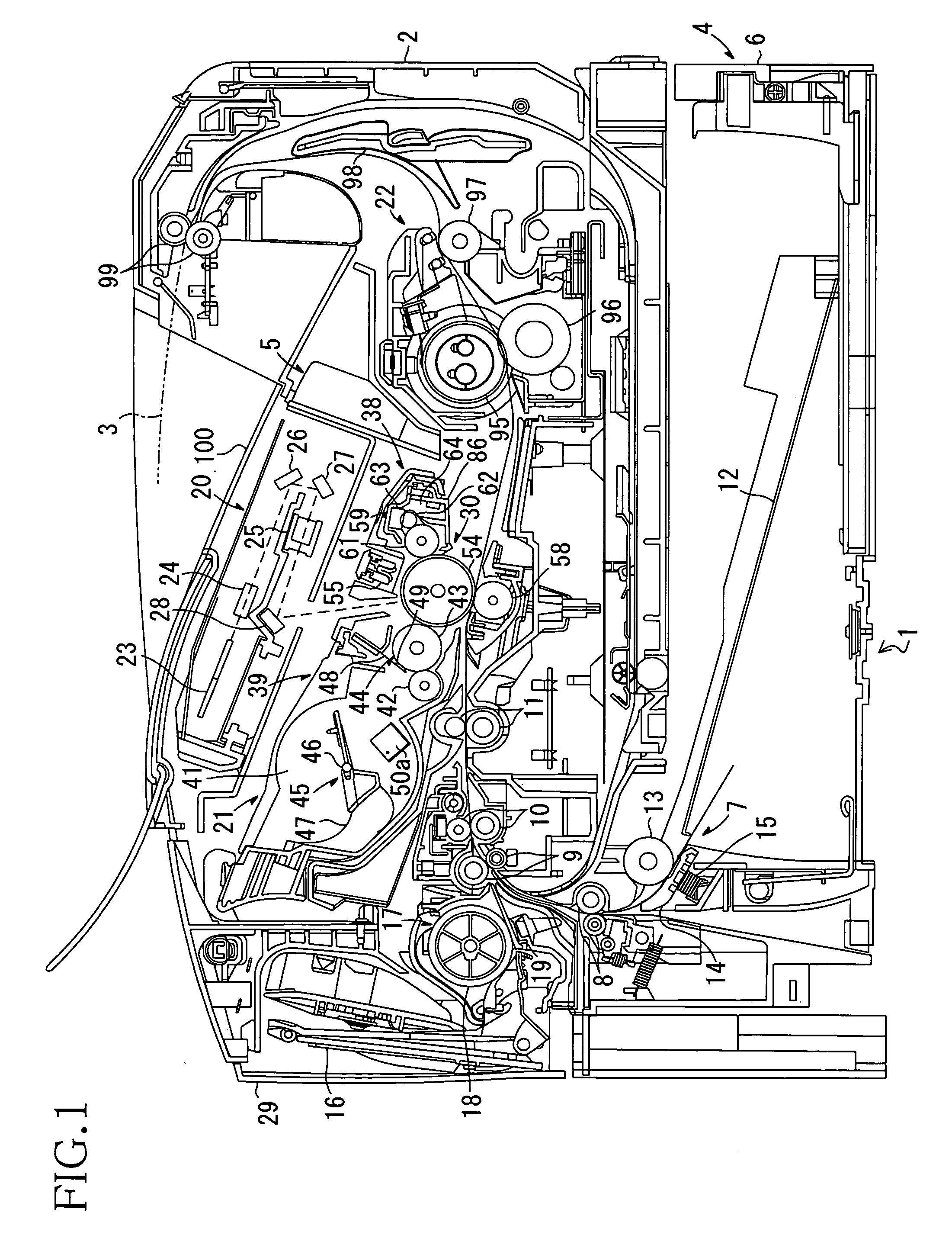
[0036] In FIG. 1, a laser printer 1 is an electrophotographic printer for forming images by non-magnetic one-component image development. The laser printer 1 includes, in a main body frame 2, a feeder unit 4 for supplying sheets 3, and an image forming portion 5 for forming images on the sheets 3 supplied.

[0037] The feeder unit 4 includes a sheet feed tray 6, which is detachably mounted at the bottom of the main body frame 2, a sheet feed mechanism 7 provided at an end of the sheet feed tray 6 (hereinafter referred to as a front side of the printer and the other end is referred to as a rear side of the printer), conveying rollers 8, 9, 10, provided downstream from the sheet feed mechanism 7 with respect to a direction in which the sheets 3 are conveyed, and resist rollers 11 provided downstream from the conveying rollers 8, 9, 10 with respect to the direction in which the sheets 3 are conveyed.

[0038] The sheet feed tray 6 has an open-top box shape so as to hold sheets 3 in layers,...


PUM


Abstract

A lever is provided in a photosensitive member frame of a photosensitive member cartridge that accommodates a developing cartridge in a cartridge accommodating portion. The lever is engaged with an engaging shaft of the developing cartridge, and is movable between a contact position and a separation position. When the lever is in the contact position, a developing roller and a photosensitive drum make contact with each other, and when the lever is in the separation position, the developing roller and the photosensitive drum are separated.

Description

BACKGROUND OF THE INVENTION [0001] 1. Field of Invention [0002] The invention relates to a developing cartridge, a photosensitive member cartridge, a process unit, and an image forming apparatus. [0003] 2. Description of Related Art [0004] Conventionally, image forming apparatuses, such as laser printers, are provided with a process unit including a drum cartridge having a photosensitive drum and a toner cartridge accommodated in the drum cartridge and having a developing roller. [0005] It is known that some process units include a separation mechanism that causes the developing roller and the photosensitive drum to make contact with each other during image developing, and keeps them separated at a warm-up. [0006] As such a process unit, Japanese Laid-Open Patent Publication No. 2003-84647 proposes to be disposed at each side of a main body case for engagement with an engaging portion provided on each side of the developing unit, for example. SUMMARY OF THE INVENTION [0007] However,...

Claims


Application Information

Patent Timeline
IPC IPC(8): G03G15/06G03G21/18
CPCG03G2221/1853G03G21/1821G03G21/181G03G21/1817G03G21/1857G03G21/1867
Inventor ISHII, MAKOTOTAKEUCHI, TAKAMIMAKINO, KAZUMASAMORI, HIROTAKA
Owner BROTHER KOGYO KK
Learn More