Illuminated electric toothbrushes emitting high luminous intensity toothbrush

Inactive Publication Date: 2005-03-10
THE PROCTER & GAMBLE COMPANY
View PDF76 Cites 78 Cited by
  • Summary
  • Abstract
  • Description
  • Claims
  • Application Information

AI Technical Summary

Benefits of technology

An illuminated electric toothbrush comprising a handle, a head, and a neck extending between the handle and the head. The handle has a hollow interior region having a motor disposed therein. The head comprises bristles and at least one light emitting diode. The light emitting diode is powered by an electrical current and has a flux density at a representative tooth surface of greater than about 30 mW/cm2 at a detector distance of ab

Problems solved by technology

However, light that is transmitted by fiber optics often diminishes in luminous intensity and/or flux density as it is transmitted.
A standard light emitting diode may be of the proper size; however such a device may not be able to deliver light having sufficient luminous intensity and/

Method used


Image

  • Illuminated electric toothbrushes emitting high luminous intensity toothbrush
  • Illuminated electric toothbrushes emitting high luminous intensity toothbrush
  • Illuminated electric toothbrushes emitting high luminous intensity toothbrush

Examples


embodiment 15

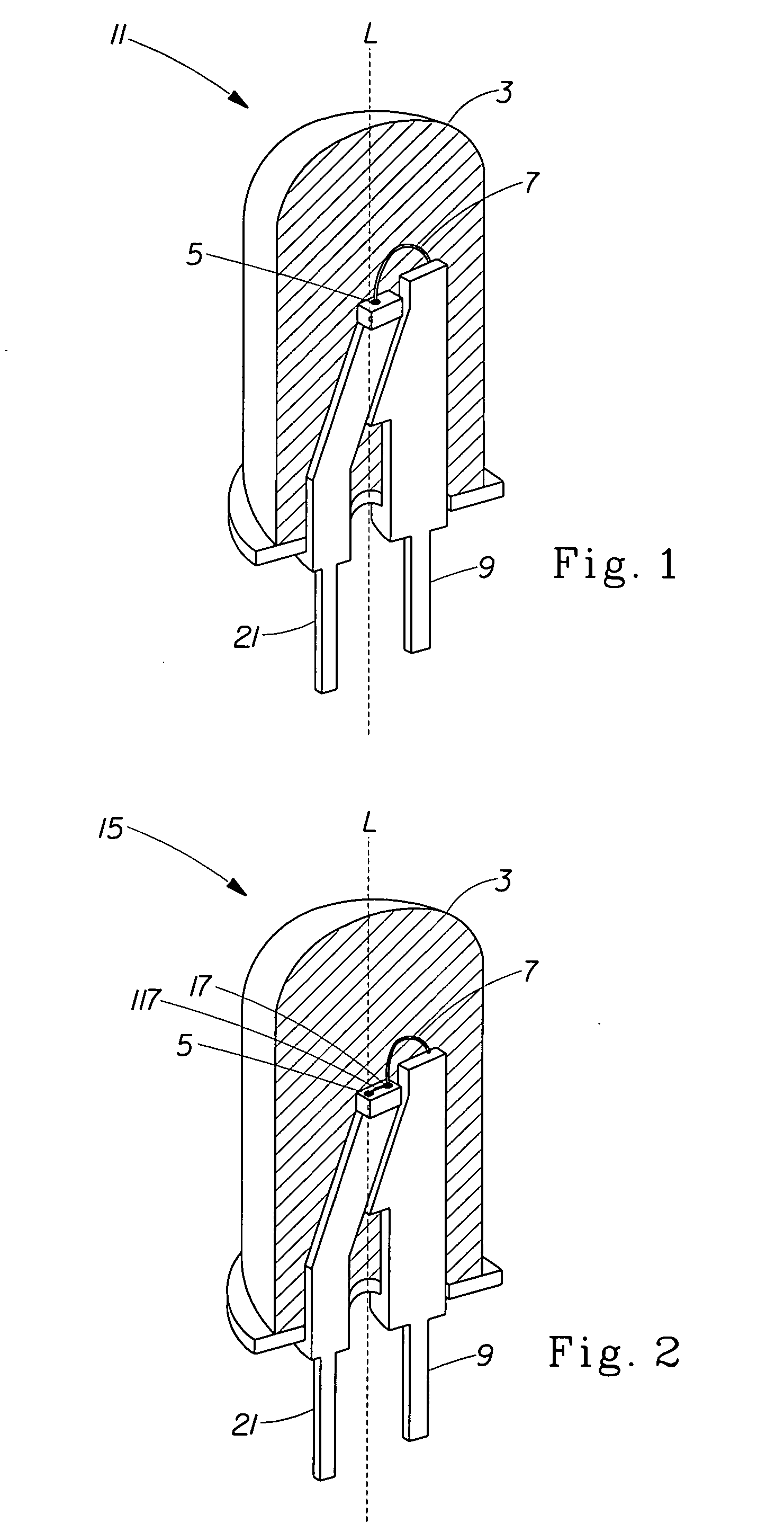
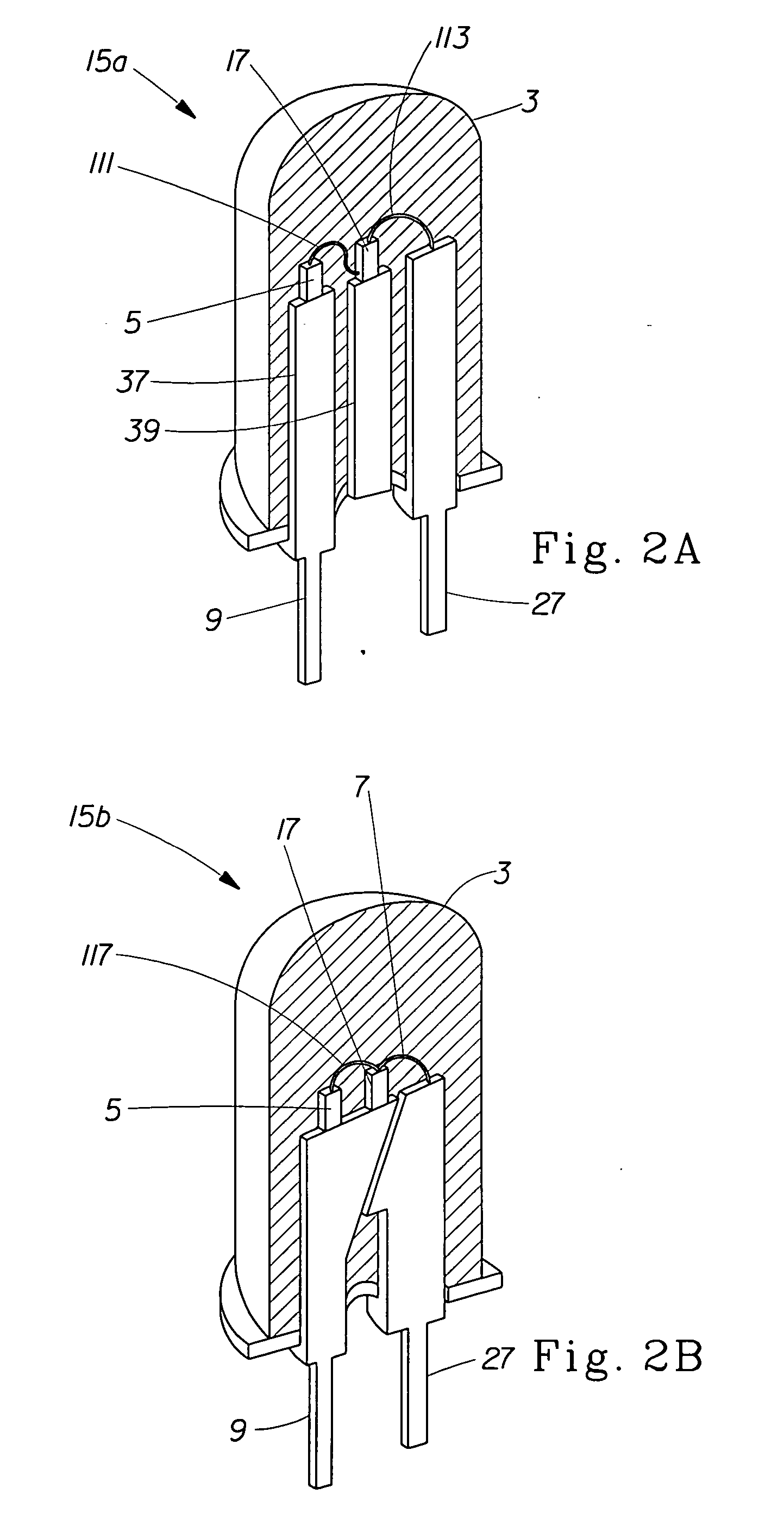
FIG. 2 shows another means for achieving the levels of luminous intensity and / or FDRT in the inventive illuminated electric toothbrush by including more than one light emitter such as multiple dices. The following embodiments illustrate LEDs having two semi-conductor substrates that emit light, such as dices, however it is contemplated that the LED could comprise more than two dices. This embodiment 15 of the invention has a single light output, the lens 3, and one positive lead 21 and one negative lead 9. However, this single standard LED package contains more than one light emitter and more than one semi-conductor substrate, and can have more than two leads. All light from the light emitting sources is combined to result in a single light output at lens 3 of LED package 15. The single LED package 15 has multiple light emitting dices 5 and 17 and a wire bonding 7 and 117. Embodiment 15 shows a connection between the dices 117. This connection can be either a parallel connection or ...

embodiment 300

In another embodiment, the LED 75 is disposed within an aperture or hole 88 that extends through the moving bristle holder 320, as best seen in embodiment 300 as shown in FIG. 7, so that the LED is stationary and the moving bristle holder 320 oscillates or rotates about the stationary LED 75. In this embodiment, the LED 75 is fixedly secured to the head 316. The LED 75 might extend partially through the hole 88 or it may be disposed below the lower surface of the moving bristle holder 320 so that it is completely contained within the head 316. The centerline or axis of the LED 75 may also be the axis of rotation or oscillation for the moving bristle holder 320. Neck 314 extends between head 316 and a handle (not shown). The head 316 further comprises static bristles 322.

In each of the above-described embodiments, the LED is disposed in, on, below or directly adjacent the moving and / or static bristle holders so that the light is directed onto the brushing area as efficiently as poss...


PUM


Abstract

An illuminated electric toothbrush comprising a light emitting diode emitting light having a flux density of at least about 30 mW/cm2. An illuminated electric toothbrush having this level of flux density can result in an oral care benefit such as whitening. When this toothbrush is used within the oral cavity the heat generated by the toothbrush remains low enough that the surface temperature of the teeth remains below about 43° C. The flux density of at least about 30 mW/cm2 can be achieved by overpowering the light emitting diode, by using a light emitting diode having at least about two dices, and by providing a pulsed or non-continuous current to the LED which results in a pulsing or non-continuous light.

Description

FIELD OF THE INVENTION The present invention relates to illuminated electric toothbrushes that utilize a light emitting diode, particularly a light emitting diode that illuminates the brushing area. More particularly, the present invention relates to the delivery of light of a particular luminous intensity or flux density that is in excess of the luminous intensity or flux density delivered by standard use of light emitting diodes. BACKGROUND OF THE INVENTION Lighted toothbrushes have traditionally been manual brushes having a light disposed on or in the handle of the toothbrush with fiber optics carrying the light from the handle to the head of the toothbrush. However, light that is transmitted by fiber optics often diminishes in luminous intensity and / or flux density as it is transmitted. Therefore, it was desired to have a light disposed in or on the head of the toothbrush such that no fiber optic materials are necessary to transmit the light. Additionally, it was desired to ha...

Claims


Application Information

Patent Timeline
IPC IPC(8): A61C17/22A61C17/26A61C17/34A61C19/06A61N5/06
CPCA61C17/22A61C17/26A61N2005/0651A61C19/066A61C17/34
Inventor PINYAYEV, ALEKSEY MIKHAILOVICHGHOSH, CHANCHAL KUMARCHAN, JOHN GEOFFREYWANG, PING
Owner THE PROCTER & GAMBLE COMPANY
Why Eureka
Try Eureka