Putter-type golf club head with an insert

a golf club head and insert technology, applied in the field of golf club heads with inserts, can solve the problem that the art has failed to provide inserts

Active Publication Date: 2005-03-10
TOPGOLF CALLAWAY BRANDS CORP
View PDF50 Cites 24 Cited by
  • Summary
  • Abstract
  • Description
  • Claims
  • Application Information

AI Technical Summary

Problems solved by technology

Further, the prior art has failed to provide an insert that may easily attach to the club head body.

Method used


Image

  • Putter-type golf club head with an insert
  • Putter-type golf club head with an insert
  • Putter-type golf club head with an insert

Examples


Embodiment Construction

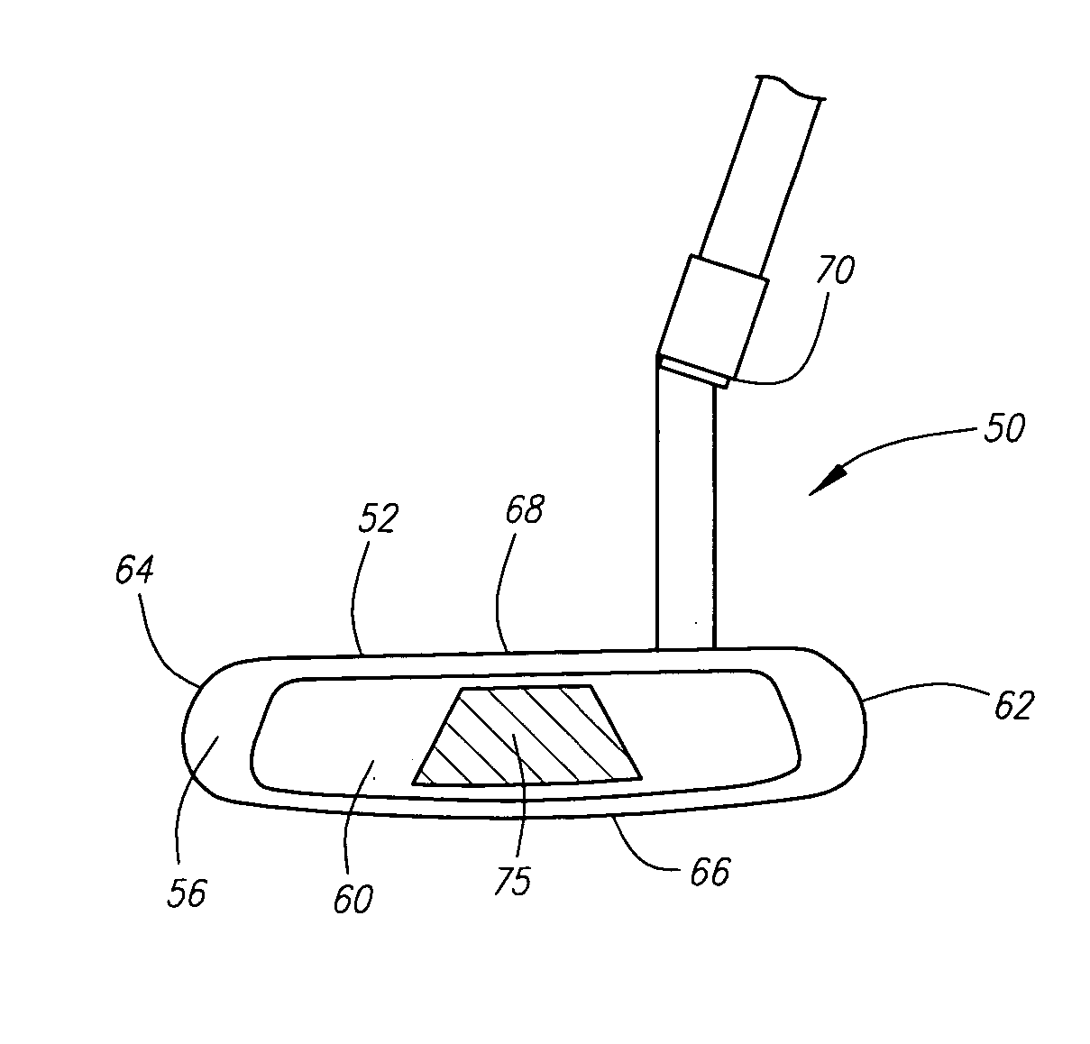
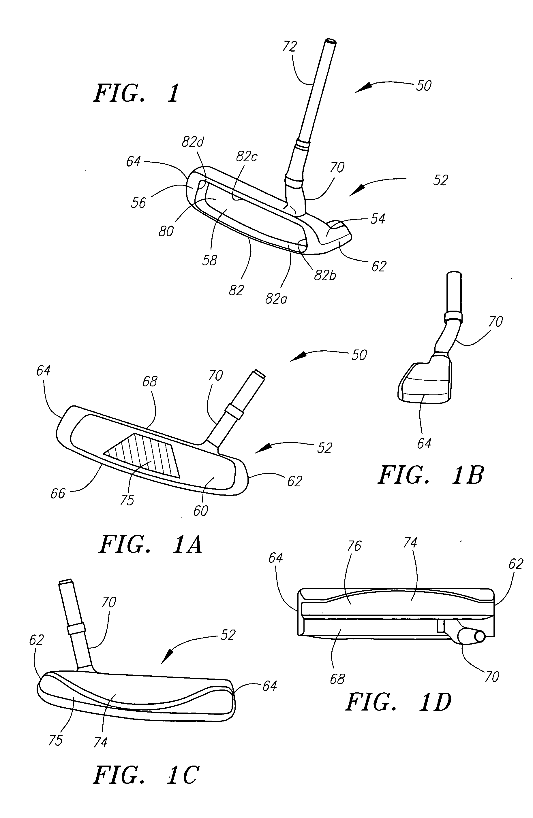
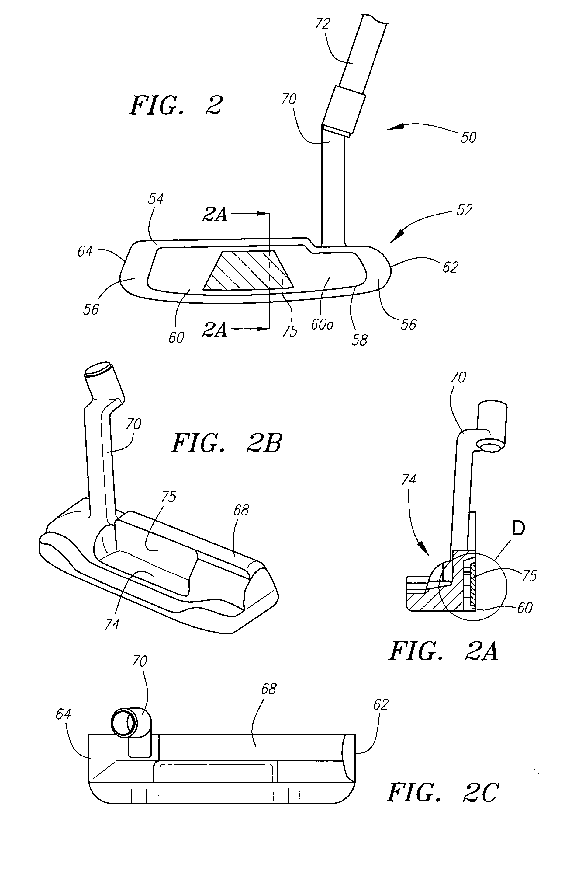
[0073] As shown in FIGS. 1 through 1D, a putter of the present invention is generally designated 50. The putter 50 includes a club head 52 having a body 54 with a front face 56 with a recess 58 therein. The club head 52 of the present invention also includes an insert 60 disposed within the recess 56. The insert 60 extends along most of the face 56 from a heel 62 of the club head 52 to a toe 64 of the club head 52, and from a sole 66 of the club head 52 to a crown 68 of the club head 52. The insert 60 has an indentation 65. A face plate 75 is disposed within the indentation 65. The club head 52 also has a hosel 70 for connection to a shaft 72. Opposite of the front face 56 of the club head 52 is a rear 74 of the club head 52.

[0074] The body 54 of the club head 52 is preferably composed of a metallic material such as stainless steel. Other metallic materials include titanium, aluminum, tungsten, zinc, magnesium, and alloys of stainless steel and tungsten. However, those skilled in t...


PUM


Abstract

A method for manufacturing a golf club head with an insert having a face plate is disclosed herein. The insert is disposed in a recess of the club head in which the recess has a depth that is greater than the thickness of the insert. The insert preferably has a plurality of tabs on its perimeter to engage the recess walls to allow the insert to essentially float within the recess. An adhesive is preferably disposed between the rear wall of the recess and an interior surface of the insert. Further, an adhesive is applied between the plurality of tabs, and preferably over the exterior surface of each of the plurality of tabs.

Description

CROSS REFERENCE TO RELATED APPLICATIONS [0001] This Application claims priority to U.S. Provisional Patent Application No. 60 / 500,743, filed on Sep. 5, 2003.FEDERAL RESEARCH STATEMENT [0002] [Not Applicable]BACKGROUND OF INVENTION [0003] 1. Field of the Invention [0004] The present invention relates to a golf club head with an insert. More specifically, the present invention relates to a putter head with a polymer insert having a face plate. [0005] 2. Description of the Related Art [0006] Throughout the history of golf, which dates back to as early as 1457, various techniques have been used to enhance the hitting characteristics of golf club heads. Golf club heads having inserts for the striking portion have been used at least as far back as 1880's when leather face irons were manufactured in Scotland. Golfer's in the 1890's were able to purchase putters with faces composed of gutta percha. More recently, inserts composed of various materials and shapes have been put forth by the cr...

Claims


Application Information

Patent Timeline
Patent Type & Authority Applications(United States)
IPC IPC(8): A63B53/04
CPCA63B53/0487A63B2053/0408A63B2053/0441A63B2053/0425A63B2209/00A63B2053/0416A63B53/0425A63B53/0441A63B53/0408A63B53/0416
Inventor BREIER, JOSHUA G.BYRNE, WAYNE H.ROLLINSON, AUGUSTIN W.HETTINGER, RONALD K.DEWANJEE, PIJUSH K.REYES, HERBERTGUARD, JOHN G.LANG, ROBERT R.OLDKNOW, ANDREW
Owner TOPGOLF CALLAWAY BRANDS CORP
Why Eureka
Try Eureka