System and method for automatically replacing nodes in a network

a technology of network nodes and automatic replacement, applied in the direction of digital transmission, data switching networks, instruments, etc., can solve the problems of limiting the system to devices, difficulty in implementing such protocols, and the replacement lonworks device is typically not configured to interface with the system

Active Publication Date: 2005-03-10
SIEMENS IND INC
View PDF6 Cites 70 Cited by
  • Summary
  • Abstract
  • Description
  • Claims
  • Application Information

AI Technical Summary

Benefits of technology

[0028] Optionally, a system according to the present invention allows an installer to identify specific NVs and CPs that must be present prior to reconfiguration.

Problems solved by technology

Alternatively, the consumer may limit the system to devices from a limited number of manufactures, all of whom employ the same protocol.
However, there are some difficulties associated with such protocols.
One such problem arises when devices are replaced with either devices from a different manufacturer or even updated devices from the same manufacturer.
However, a replacement LonWorks device is typically not configured to interface with a system in the same manner as the LonWorks device being replaced.
However, such storage obviously requires memory space.
Thus, due to memory constraints, some nodes do not include NV names in the self-documentation stored within the nodes.
However, in the event the replacement component has a different Program ID, such as may occur when adding functionality, switching manufacturers, or providing an entirely new functionality, prior art network management tools assume the node to be different, and do not automatically attempt to establish the logical connections to the device.
Moreover, if the original network management database is not available and a network image cannot be recovered by the network management tool, then the node must be manually configured.
Obviously, manually configuring the node is labor intensive in engineering and testing and prone to error.
The problems are exacerbated if more than one component is replaced at the same time.

Method used


Image

  • System and method for automatically replacing nodes in a network
  • System and method for automatically replacing nodes in a network
  • System and method for automatically replacing nodes in a network

Examples


Embodiment Construction

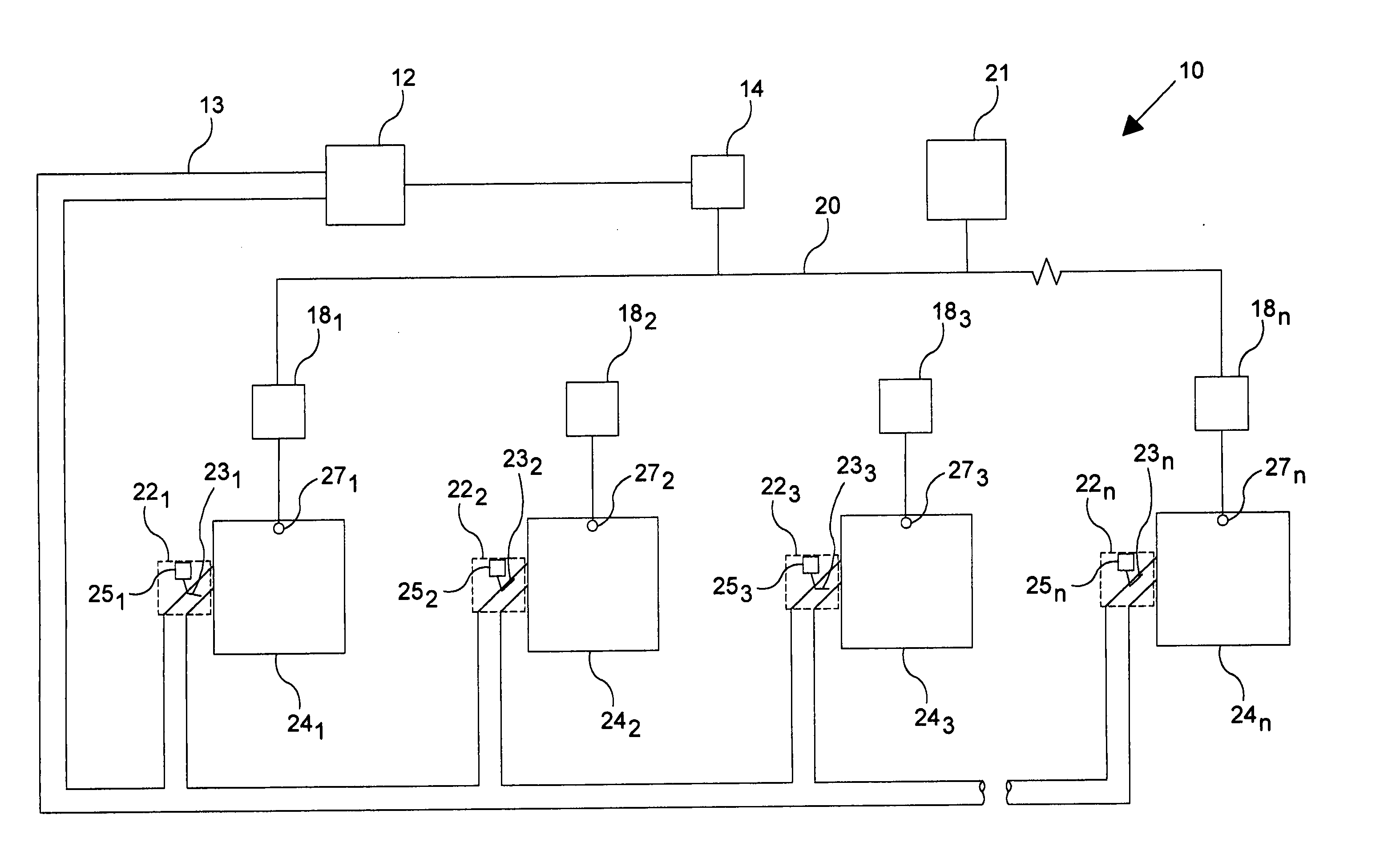
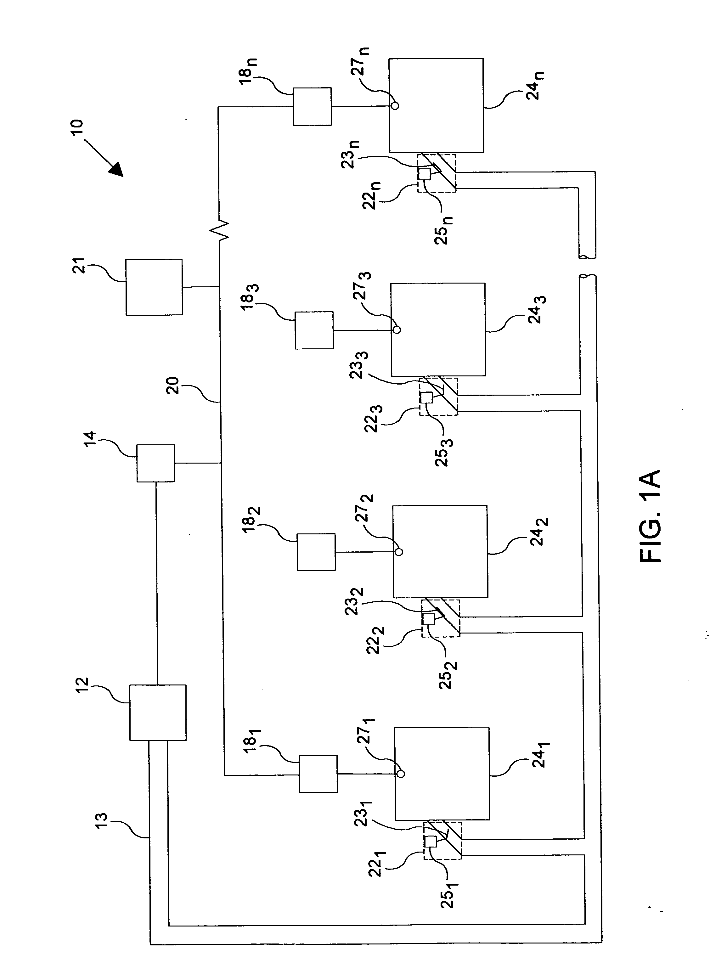
[0041]FIG. 1a shows an exemplary air distribution system 10 in which an air-handling unit (AHU) controller 14 controls the operation of AHU 12. Controller 14 is coupled as a sink controller through a network 20 to a plurality of variable air volume (VAV) controllers 18l . . . 18n that operate VAV terminals 22l . . . 22n bringing conditioned air to local spaces 24l . . . 24n. VAV terminals 22l . . . 22n place dampers 23l . . . 23n in one of a plurality of positions between a fully open position and a minimum allowed open position.

[0042] Dampers are typically not allowed to be fully shut in order to ensure there is some fresh air supplied to a space, even if the temperature will be driven out of a desired range. This may be a needed safety measure, for example, to ensure an adequate amount of oxygen is supplied to each space. The minimum allowed open position may thus be set by a CP for the distribution system based upon the most restricted space. That is, the system's minimum allowe...


PUM


Abstract

A network tool is provided for use when replacing devices in an automatically controlled distributed processing system. The network tool reestablishes all or a portion of the logical connections formerly provided to the node where the replacement device is or will be located. The tool compares data associated with the logical connections of the node and data associated with the logical connections for the replacement device to determine proper logical connection. In one embodiment, the compared data comprises network variables and configuration properties.

Description

[0001] This application claims the benefit of and / or priority to U.S. provisional application Ser. No. 60 / 492,641 filed Aug. 5, 2003.FIELD OF THE INVENTION [0002] The present invention relates to distributed processing in automation control systems, and in particular, to automation control systems that use network variables and configuration properties to facilitate distributed processing. BACKGROUND OF THE INVENTION [0003] Automation control systems are well-known. Such systems include building automation systems for controlling environmental equipment, fire and safety equipment, security equipment, elevator banks, and the like. Other automation control systems include industrial control, food processing, and transportation systems. In general, these systems receive data from sensors that are evaluated to determine control actions to take in order to bring about some condition or perform some operation. For example, an environmental control system uses sensors to detect environment...

Claims


Application Information

Patent Timeline
Patent Type & Authority Applications(United States)
IPC IPC(8): H04L12/24H04L29/06H04L29/08
CPCH04L29/06H04L41/0663H04L41/0843H04L69/329H04L43/0811H04L67/303H04L67/125H04L41/0846H04L9/40
Inventor FRUTIGER, THEOCOOGAN, JAMES J.CHERNY, ALEX
Owner SIEMENS IND INC
Why Eureka
Try Eureka