

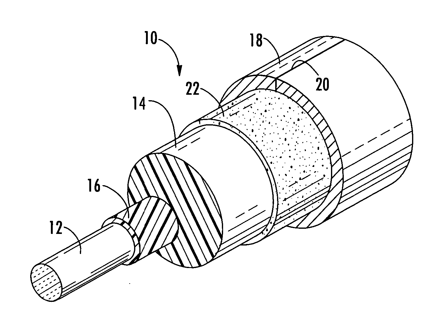
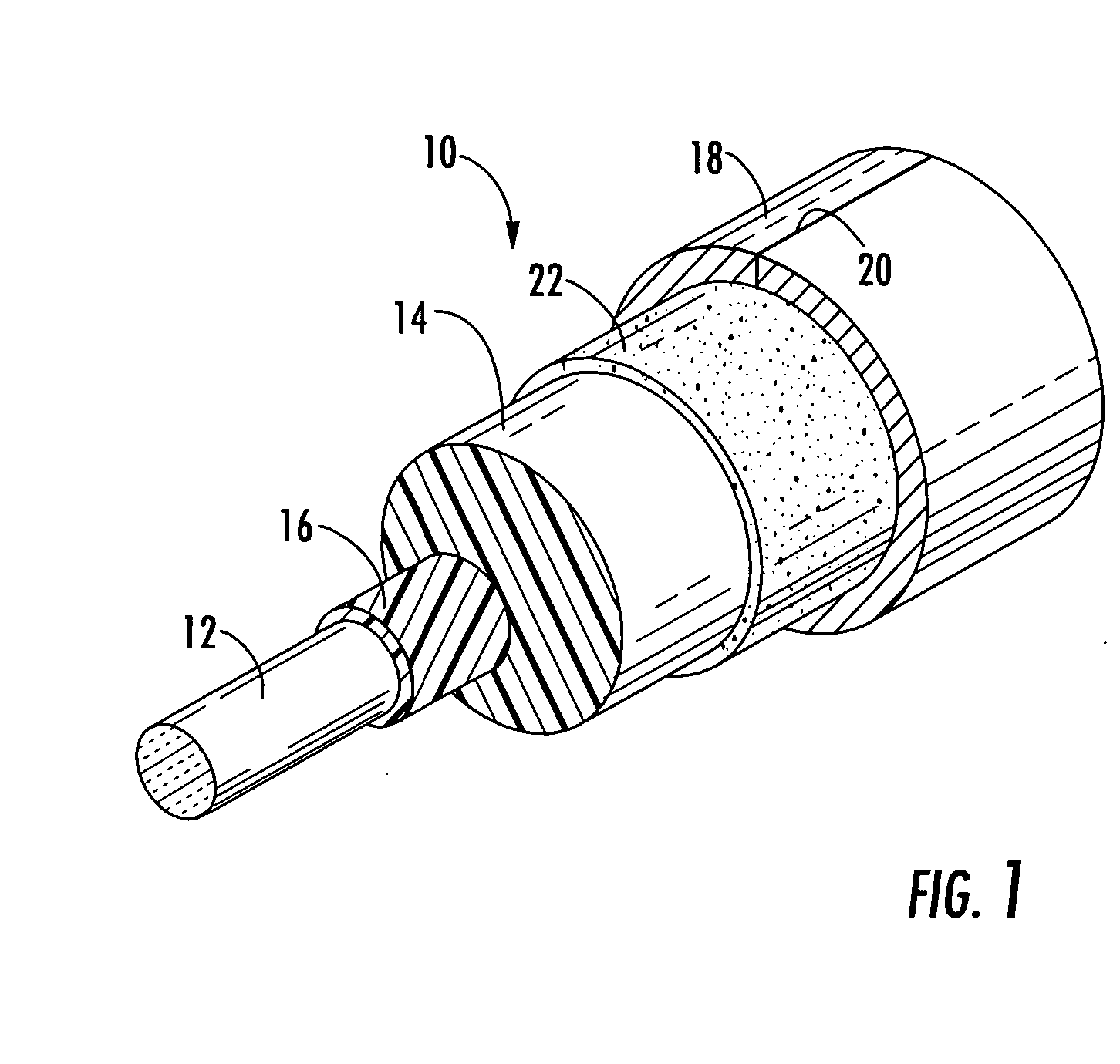
Coaxial cable with strippable center conductor precoat
a center conductor and precoat technology, applied in the direction of power cables, cables, insulation conductors/cables, etc., can solve the problems of increasing rf attenuation, affecting the performance of coaxial cables, and common center conductor sucking, etc., to achieve the elimination of a source of cable damage, facilitate the removal of the precoat layer, and facilitate the effect of splicing operations
- Summary
- Abstract
- Description
- Claims
- Application Information
AI Technical Summary
Benefits of technology
Problems solved by technology
Method used
Image

Examples
example
A precoat composition was formulated by compounding the following constituents: 97.5% of a 80 MI low density polyethylene 2.5% of a 5.5 MI ethylene acrylic acid copolymer (6.5% acrylic acid content)
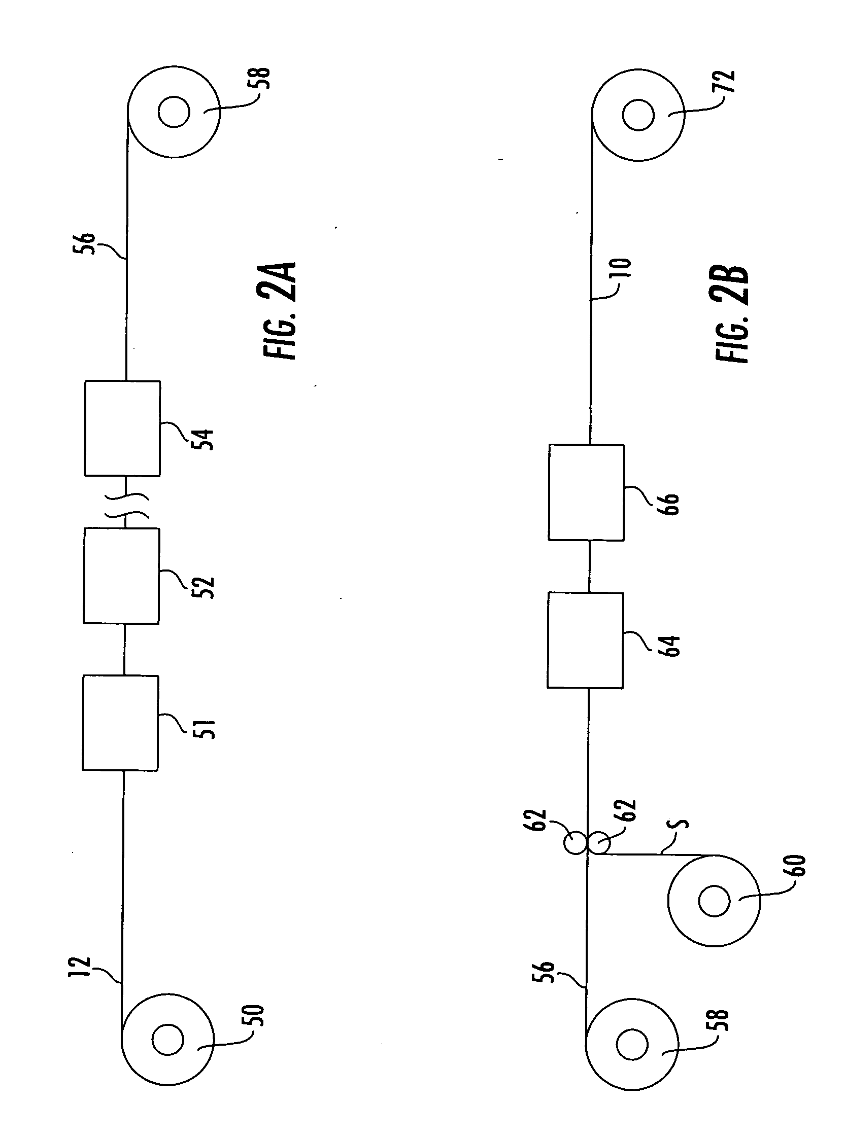
This composition was applied to copper-clad aluminum conductors of a diameter ranging from 0.1085 to 0.2025 inch in accordance with the following procedures and conditions: The center conductor was preheated to 125° F. The composition was applied in a controlled thickness using a polymer extrusion process. The thickness of the application was controlled to a nominal average thickness of 0.008 inches. This structure allowed to cool to near ambient temperature and was then passed through a foaming polymer extrusion process to apply a closed cell foam polyethylene dielectric layer.
The specimens were tested by the test procedures described above to determine the shear force needed to disrupt the bond in both the axial and rotational modes, and the results are given in the following tab...
PUM
| Property | Measurement | Unit |
|---|---|---|
| Temperature | aaaaa | aaaaa |
| Temperature | aaaaa | aaaaa |
| Temperature | aaaaa | aaaaa |
Abstract
Description
Claims
Application Information