Brake control device improving driver's brake feeling

a technology of brake control and driver's feeling, which is applied in the direction of brake types, automatic initiation, braking systems, etc., can solve the problems of driver's unease, deceleration speed, and deceleration speed generated by automatic brakes temporarily reduced,

Inactive Publication Date: 2005-03-17
ADVICS CO LTD
View PDF8 Cites 17 Cited by
  • Summary
  • Abstract
  • Description
  • Claims
  • Application Information

AI Technical Summary

Benefits of technology

A main object of the present invention is to provide a vehicular brake control device that can perform a brake control so as to generate a brake feeling that accords with a driver's expectations by adjusting a deceleration speed when an automatic brake is switched to a manual brake.

Problems solved by technology

However, according to the disclosure of Japanese Patent Publication No. 2000-313322, when the brake fluid pressure applied to the wheel cylinder is released by the operation of the manual brake, the deceleration speed generated by the automatic brake is temporarily reduced, and deceleration speed inconsistency, namely, a fall in the deceleration speed, may result.
As a result of this reduction, the driver feels a sense of unease, i.e., feels that the braking force is weakened, and is not able to obtain a brake feeling that meets with the driver's expectations.
In this case, the vehicle body deceleration is increased, and the driver may feel a sense of unease due to the sudden braking force.

Method used


Image

  • Brake control device improving driver's brake feeling
  • Brake control device improving driver's brake feeling
  • Brake control device improving driver's brake feeling

Examples


first embodiment

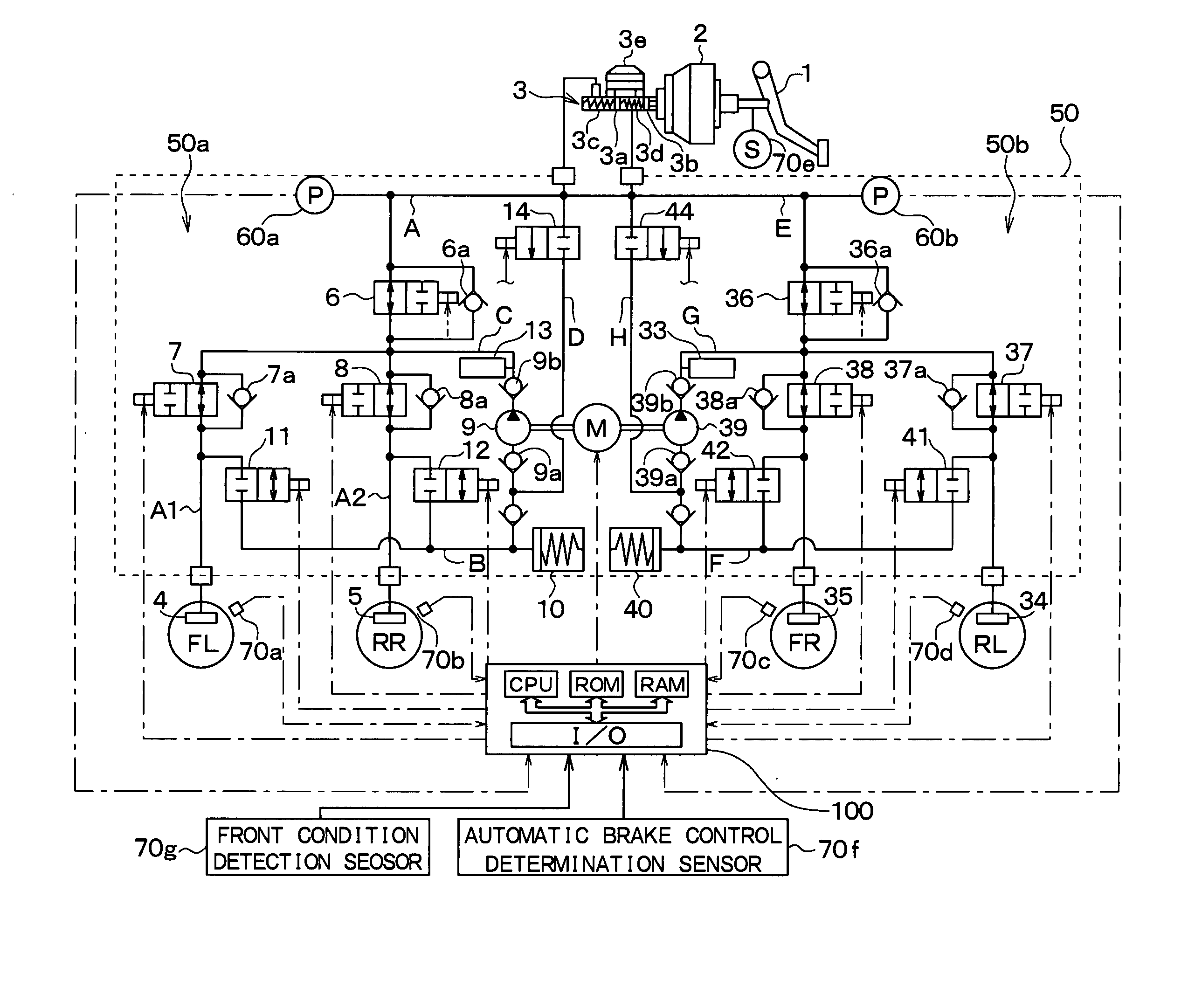
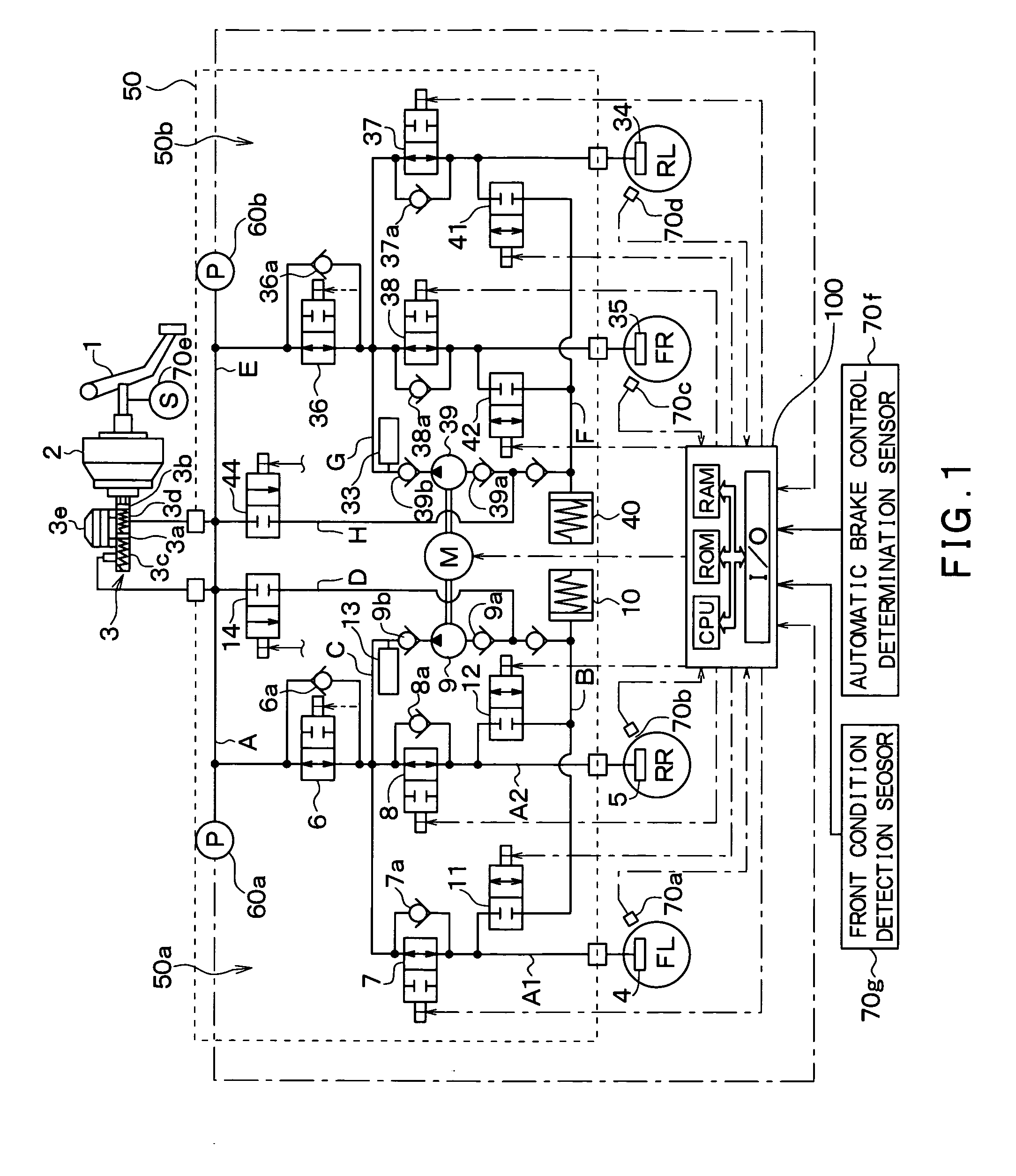
Next, a first embodiment of the present invention will be described with reference to drawings.FIG. 1 schematically shows a brake system including a brake fluid pressure control device. The basic structure of the brake system according to the first embodiment of the present invention will be described with reference to FIG. 1.

In the first embodiment of the present invention, the brake fluid pressure control device is mounted in a vehicle having two hydraulic piping systems (a diagonal split system), i.e., a first piping system 50a for controlling a brake fluid pressure applied to a front left wheel FL and a rear right wheel RR, and a second piping system 50b for controlling a brake fluid pressure applied to a right front wheel RF and a rear left wheel LR.

Referring to FIG. 1, when a brake pedal 1 that acts as a brake control unit is depressed by a driver, a braking force is applied to the vehicle. The brake pedal 1 is connected to a brake booster 2 that functions as a brake flui...


PUM


Abstract

A lower limit of a target value of a wheel cylinder pressure generated by a wheel cylinder is set as a first value PT1. Specifically, the first value PT1 is determined based on the application pressure generated by the wheel cylinder during an automatic brake control. Accordingly, the actual application pressure generated can be set to be equal to or more than the first value PT1. Thus, it is possible to prevent the application pressure from being decreased unintentionally when the automatic brake control is switched to a manual brake control, and thus, it is possible to maintain a deceleration speed of a vehicle at the level of a vehicle body deceleration generated during the automatic brake control. Accordingly, it is less likely that the driver will be caused to feel a sense of unease by weakening of the braking force.

Description

CROSS REFERENCE TO RELATED APPLICATION This application is based upon and claims the benefit of Japanese Patent Application No. 2003-319817 filed on Sep. 11, 2003, the content of which are incorporated herein by reference. FIELD OF THE INVENTION The present invention relates to a vehicular brake control device that improves the brake feeling of a driver by adjusting deceleration generated by an automatic brake and a manual brake. BACKGROUND OF THE INVENTION Japanese Patent Publication No. 2000-313322 discloses a related vehicular brake control device that aims to achieve a good brake feeling when a manual brake is operated during automatic braking. The brake control device has a relief valve for releasing brake fluid, and is thus able to release brake fluid pressure applied to a wheel cylinder by the manual brake. When a brake pedal is operated during automatic braking, the opening of the relief valve is controlled in accordance with a release time. This release time is determine...

Claims


Application Information

Patent Timeline
Patent Type & Authority Applications(United States)
IPC IPC(8): B60T7/12B60T8/00B60T8/48
CPCB60T8/4872Y10S303/02Y10S303/01
Inventor KUDO, KEN
Owner ADVICS CO LTD
Why Eureka
Try Eureka