Boundary acoustic wave device

a boundary acoustic wave and acoustic wave technology, applied in the direction of sonic/ultrasonic/infrasonic transmission, electrical apparatus, transmission, etc., can solve the problems of increasing the cost of the surface acoustic wave device, and the difficulty of miniaturizing the two-dimensional area of the boundary acoustic wave device to less than 1 mm, and achieve excellent characteristics and performan

Inactive Publication Date: 2005-03-17
MURATA MFG CO LTD
View PDF5 Cites 58 Cited by
  • Summary
  • Abstract
  • Description
  • Claims
  • Application Information

AI Technical Summary

Benefits of technology

[0014] To overcome the problems described above, preferred embodiments of the present invention provide a boundary acoustic wave device that satisfies miniaturization requirements of element size and has excellent characteristics and performance.

Problems solved by technology

The use of the package having the cavity increases the cost of the surface acoustic wave device.
These elements make it difficult to miniaturize the two dimensional area of the boundary acoustic wave device to less than 1 mm2.

Method used


Image

  • Boundary acoustic wave device
  • Boundary acoustic wave device
  • Boundary acoustic wave device

Examples


Embodiment Construction

[0064] Preferred embodiments of the present invention will now be described.

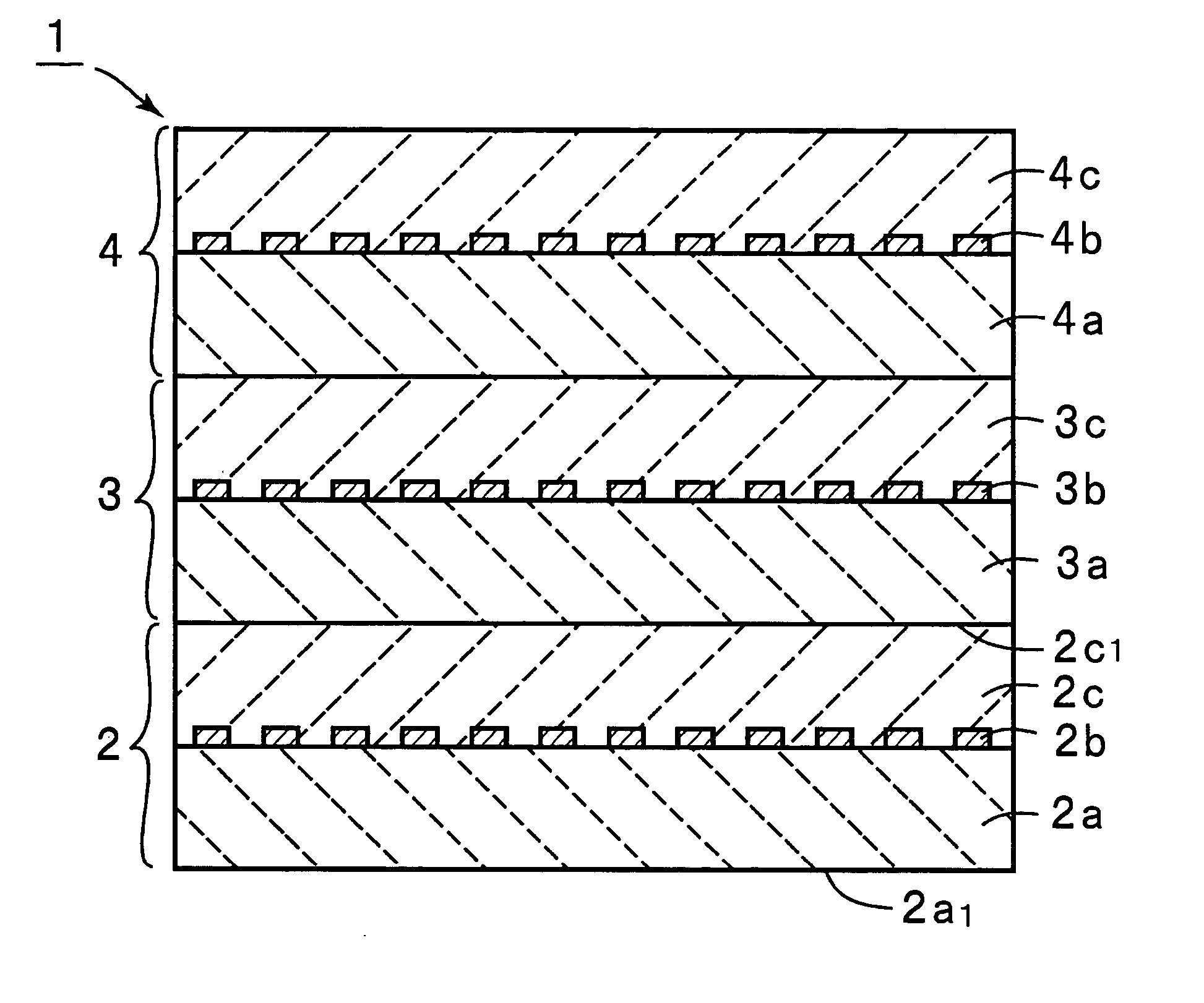
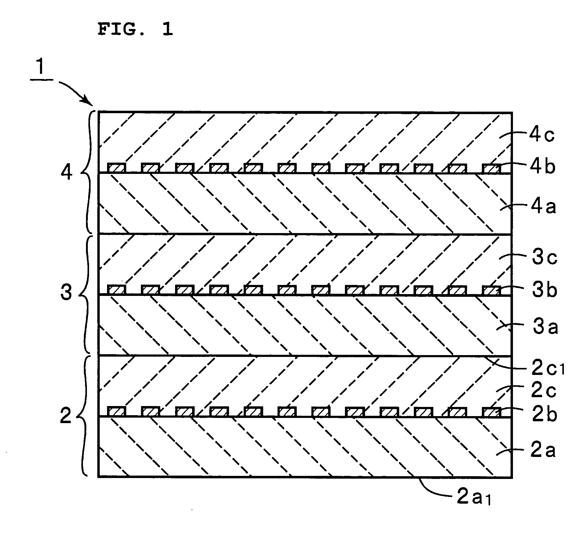
[0065]FIG. 1 is a front sectional view illustrating a boundary acoustic wave device 1 in accordance with a first preferred embodiment of the present invention. The boundary acoustic wave device 1 includes a laminate structure including a plurality of boundary acoustic wave elements 2-4. The boundary acoustic wave elements 2-4 are laminated such that boundary acoustic wave propagating surfaces thereof are substantially parallel with each other. If the elements 2-4 are bonded using a bonding agent, the boundary acoustic wave propagating surfaces of upper and lower boundary acoustic wave elements will not be parallel to each other due to variations in thickness of the bonding agent. The boundary acoustic wave propagating surfaces may have an angle of ±30 degrees therebetween. In the first preferred embodiment, the boundary acoustic wave elements 2-4 are preferably identically manufactured. In the boundary acou...


PUM


Abstract

A boundary acoustic wave device includes a first boundary acoustic wave element, and a second boundary acoustic wave element disposed on the first boundary acoustic wave element. Each boundary acoustic wave element includes a first solid layer made of a piezoelectric material, a second solid layer made of one of a piezoelectric material and an insulating material, and disposed on the first solid layer, and a boundary acoustic wave exciting interdigital transducer arranged in the boundary between the first and second solid layers.

Description

BACKGROUND OF THE INVENTION [0001] 1. Field of the Invention [0002] The present invention relates to a boundary acoustic wave device using a boundary acoustic wave traveling in a boundary between two solid layers and, in particular, to a boundary acoustic wave device having a laminate structure in which one boundary acoustic wave element or one surface acoustic wave element is laminated to at least another boundary acoustic wave element. [0003] 2. Description of the Related Art [0004] A variety of surface acoustic wave devices have been conventionally used for an RF filter and an IF filter for cellular phones, a VCO resonator, and a VIF filter for televisions. The surface acoustic wave devices use a surface acoustic wave such as a Reyleigh wave or a first leakage wave traveling along the surface of a medium. [0005] The surface acoustic wave is sensitive to variations in the state of the surface of the medium because the surface acoustic wave travels along the surface of the medium. ...

Claims


Application Information

Patent Timeline
Patent Type & Authority Applications(United States)
IPC IPC(8): H03H3/08H03H9/145H03H9/02H03H9/25
CPCH03H9/6483H03H9/0222
Inventor KANDO, HAJIME
Owner MURATA MFG CO LTD
Why Eureka
Try Eureka