Electrostatic quadrupole deflector for microcolumn

a quadrupole deflector and microcolumn technology, applied in the manufacture of electrode systems, electric discharge tubes/lamps, electric discharge tubes, etc., can solve the problems of reducing the effective deflector field size, and achieve the effect of simple driving system, good characteristics and performan

Active Publication Date: 2017-05-30
IND UNIV COOP FOUND SUNMOON UNIV
View PDF28 Cites 0 Cited by
  • Summary
  • Abstract
  • Description
  • Claims
  • Application Information

AI Technical Summary

Benefits of technology

[0015]Accordingly, the present invention has been made keeping in mind the above problems occurring in the related art, and an object of the present invention is to improve a deflection characteristic of a deflector. Another object of the present invention is to provide a structure of a deflector that can be more easily fabricated using a conventional fabrication method and that can increase an effective deflection field size. A further object of the invention is to provide a method for driving a deflector having the same structure.
[0022]The deflector according to the invention is structurally stable like a conventional octupole deflector and has a simple driving system like a conventional quadrupole deflector while having good characteristics and performance.

Problems solved by technology

The increase in the spot size results in deterioration in resolution, causing a decrease in effective deflection field size.

Method used


Image

  • Electrostatic quadrupole deflector for microcolumn
  • Electrostatic quadrupole deflector for microcolumn
  • Electrostatic quadrupole deflector for microcolumn

Examples


Embodiment Construction

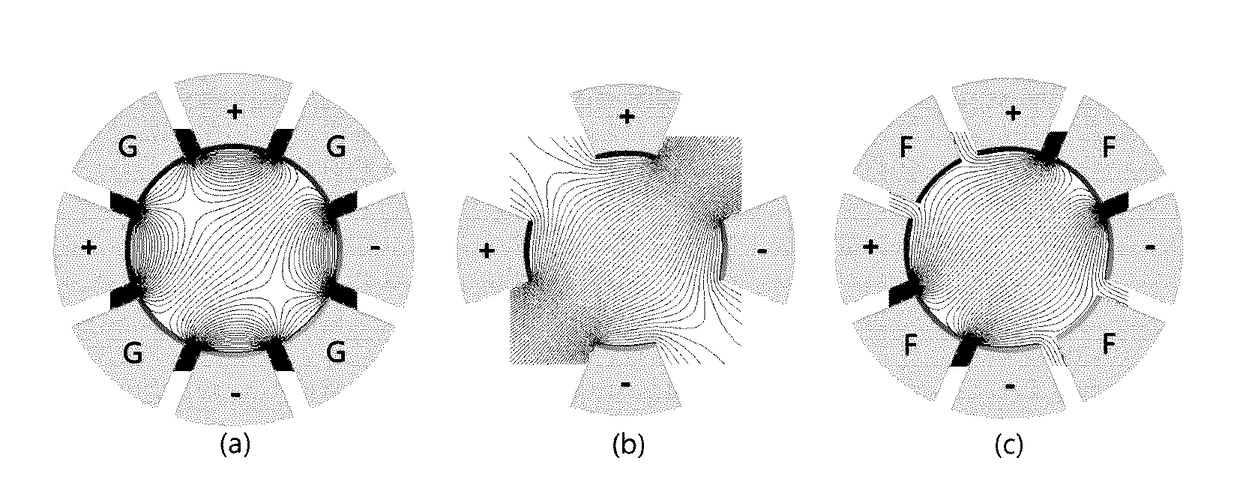
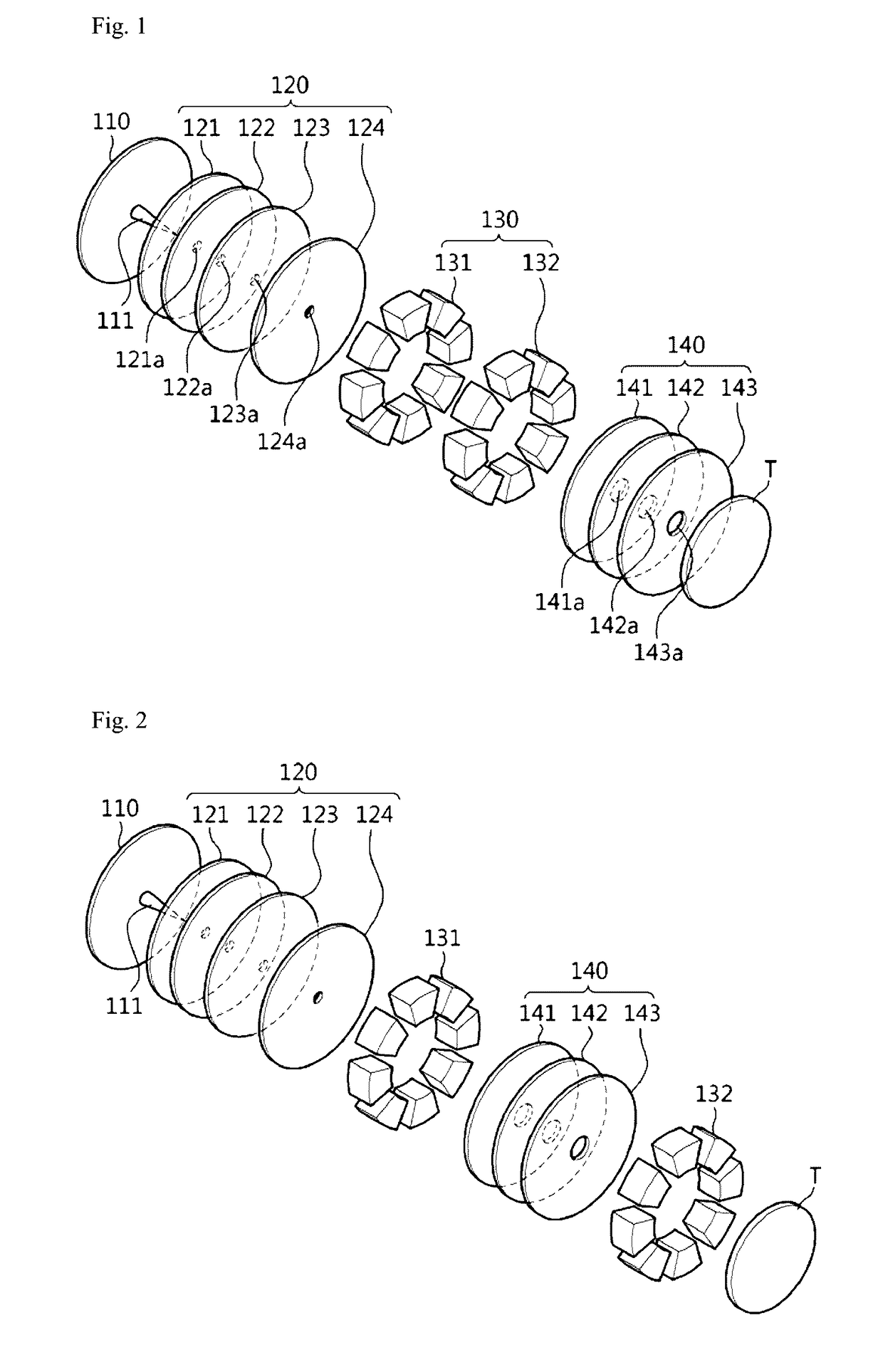
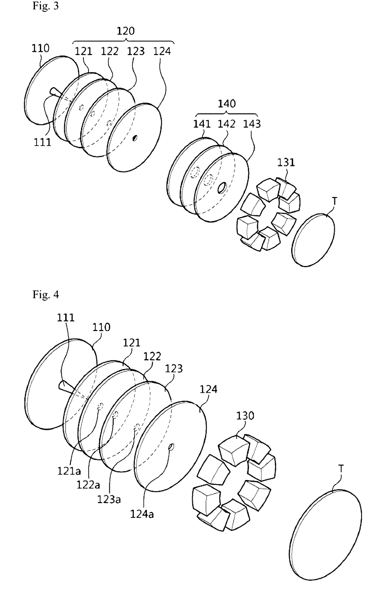
[0033]A preferred embodiment of the present invention to improve deflection characteristics of a deflector for a microcolumn provides a quadrupole deflector that is shown in FIG. 6. The quadrupole deflector for a microcolumn according to the preferred embodiment appears to be similar to a conventional octupole deflector in terms of appearance but is different in driving method of deflecting an electron beam. That is, four deflecting electrodes 1-1, 1-2, 1-3, and 1-4 are used to deflect an electron beam, and floating electrodes 2 are interposed between respective deflecting electrodes in an alternate manner, with a predetermined gap 6 between a deflecting electrode and a floating electrode.

[0034]A deflector according to the preferred embodiment of the invention will be described with reference to FIG. 6. Arc-shaped deflecting electrodes 1 are radially arranged by cutting a doughnut-shaped plate into pieces. That is, four deflecting electrodes 1 are arranged around an electron beam pa...


PUM


Abstract

Disclosed is an electrostatic quadrupole deflector for a microcolumn. The deflector includes an electron beam passage hole, deflecting electrodes to which a deflection voltage is applied, and floating electrodes to which the deflection voltage is not applied. The deflector is structurally stable and has a simple driving system. The deflector has good performance and characteristics.

Description

BACKGROUND OF THE INVENTION[0001]Field of the Invention[0002]The present invention relates to a deflector for a microcolumn and, more particularly, to an electrostatic quadrupole deflector.[0003]Description of the Related Art[0004]Currently, microcolumns are applied to devices that use an electron beam, such as electron microscopes, as well as to manufacturing equipments or testers that are used in semiconductor or display industry.[0005]FIG. 1 is a perspective view showing the structure of a micro-electron optical column according to a related art. The micro-electron optical column (also referred to as micro-electron column) includes an electron emission source 110, a source lens 120 including four electrodes 121, 122, 123, and 124, a deflector 130, and a focusing lens 140 including electrodes 141, 142, and 143. The electrodes have respective electron passage holes 121a, 122a, 123a, 124a, 141a, 142a, and 143a. The source lens 120 and the focusing lens (or einzel lens) 140 each incl...

Claims


Application Information

Patent Timeline
Patent Type & Authority Patents(United States)
IPC IPC(8): H01J37/147H01J37/073H01J37/26H01J9/02
CPCH01J37/1477H01J9/02H01J37/073H01J37/26H01J2237/04924H01J2237/1516
Inventor OH, TAE SIKKIM, HO SEOBKIM, DAE WOOK
Owner IND UNIV COOP FOUND SUNMOON UNIV
Why Eureka
Try Eureka