Liquid crystal display device

a liquid crystal display and display screen technology, applied in the direction of mirrors, instruments, polarising elements, etc., can solve the problems of unnatural coloring, lowered contrast, and inability to achieve sufficient viewing angle characteristics, so as to achieve the effect of achieving the desired viewing angle characteristic without increasing the manufacturing cos

Inactive Publication Date: 2005-03-17
JAPAN DISPLAY CENTRAL CO LTD
View PDF3 Cites 33 Cited by
  • Summary
  • Abstract
  • Description
  • Claims
  • Application Information

AI Technical Summary

Benefits of technology

[0010] An object of this invention is to provide a liquid crystal display device which can solve the above problems and attain a preferable viewing angle characteristic without increasing the manufacturing cost.
[0014] In the above liquid crystal display devices, the number of films required for viewing angle compensation can be sufficiently reduced and a manufacturing process for the films can be made simple. Therefore, a preferable viewing angle characteristic can be attained without increasing the manufacturing cost.

Problems solved by technology

However, the above improvement measures cannot make it possible to attain a sufficient viewing angle characteristic when the display device is viewed from an orientation or direction other than the front.
That is, there occurs a problem that coloring becomes unnatural, the contrast is lowered or display of black and white is reversed.
However, the conventional viewing angle compensation system has a large number of problems that the compensation effect is not sufficient, the cost becomes extremely high by using a plurality of expensive films, and at the same time, the thickness and weight of the liquid crystal display device are increased and mass production is difficult to attain because films which cannot be formed by a simple manufacturing process are used, for example.

Method used


Image

  • Liquid crystal display device
  • Liquid crystal display device
  • Liquid crystal display device

Examples


Embodiment Construction

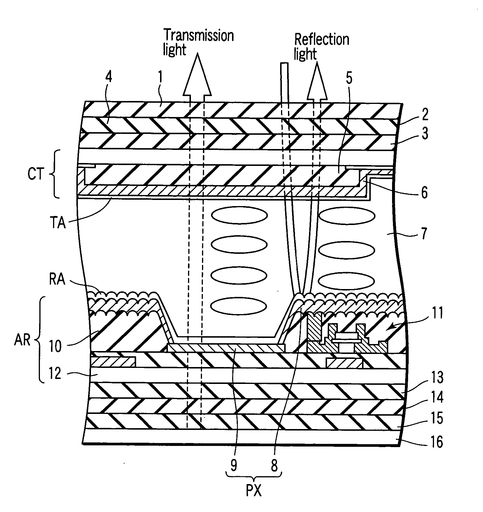
[0025] There will now be described in detail a semi-transmission type liquid crystal display device according to a first embodiment of this invention with reference to the accompanying drawings.

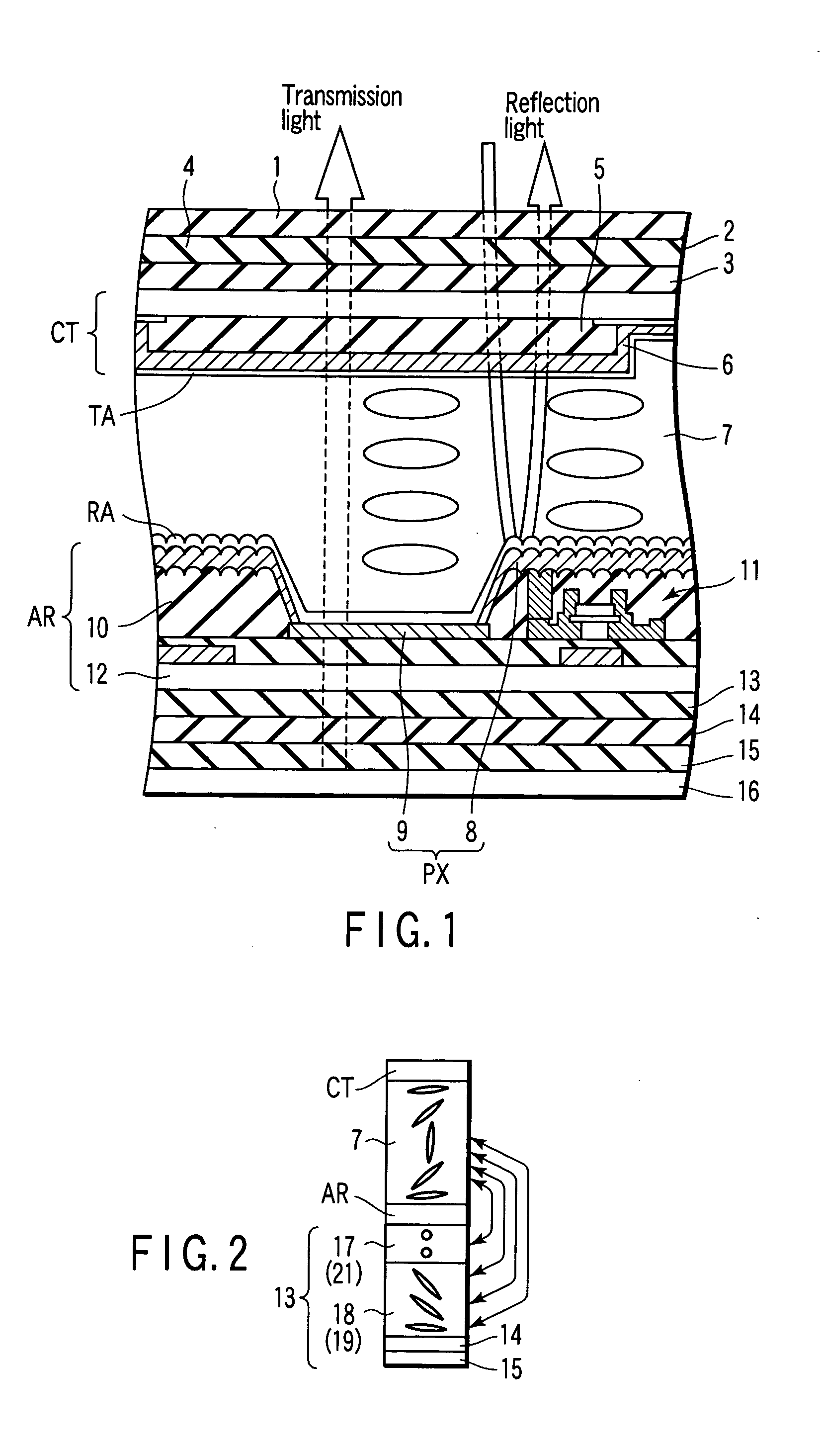
[0026]FIG. 1 shows the cross sectional structure of the semi-transmission type liquid crystal display device. The semi-transmission type liquid crystal display device includes first and second electrode substrates AR, CT, a liquid crystal layer 7 which is held between the electrode substrates and in which nematic liquid crystal molecules are arranged in substantially parallel to each of the electrode substrates AR, CT without distortion, first and second optical anisotropic elements 3, 13 respectively disposed on the electrode substrates CT, AR on the sides opposite to the liquid crystal layer 7, first and second half-wavelength plates (which are hereinafter expressed as λ / 2 plates) 2, 14 respectively disposed on the optical anisotropic elements 3, 13, first and second polarizing plates 1, 1...


PUM

PropertyMeasurementUnit
angleaaaaaaaaaa
tilt angleaaaaaaaaaa

Abstract

A liquid crystal display device includes first and second electrode substrates, a liquid crystal layer which is held between the substrates and in which nematic liquid crystal molecules are arranged in substantially parallel to each of the substrates without distortion, first and second optical anisotropic elements respectively disposed on the substrates on the sides opposite to the liquid crystal layer, first and second half-wavelength plates respectively disposed on the optical anisotropic elements, and first and second polarizing plates respectively disposed on the half-wavelength plates. Particularly, the substrate includes a light transmitting section which permits backlight light from the polarizing plate side to transmit therethrough and a light reflecting section which reflects ambient light from the polarizing plate side and at least one of the optical anisotropic elements is formed of two retardation plates having a retardation in a plane.

Description

CROSS-REFERENCE TO RELATED APPLICATIONS [0001] This is a Continuation Application of PCT Application No. PCT / JP03 / 05463, filed Apr. 28, 2003, which was published under PCT Article 21(2) in Japanese. [0002] This application is based upon and claims the benefit of priority from prior Japanese Patent Application No. 2002-129996, filed May 1, 2002, the entire contents of which are incorporated herein by reference.BACKGROUND OF THE INVENTION [0003] 1. Field of the Invention [0004] The present invention relates to a liquid crystal display device using backlight light together with ambient light to provide a display. [0005] 2. Description of the Related Art [0006] In recent years, liquid crystal display devices are applied to various fields of notebook personal computers, monitors, car navigations, mid- or small-size TV, portable telephones and the like. Among them, a reflection type liquid crystal display device does not require a backlight, and therefore, application thereof to a display...

Claims


Application Information

Patent Timeline
Patent Type & Authority Applications(United States)
IPC IPC(8): G02B5/30G02F1/1335G02F1/13363G02F1/139
CPCG02F1/133555G02F2413/105G02F2001/133638G02F1/1393G02F1/133638G02B5/08G02B5/30G02F1/13363
Inventor OOTAKE, TOSHIYANAKAI, YUTAKAKIZU, YUKOYAMADA, YOSHITAKA
Owner JAPAN DISPLAY CENTRAL CO LTD
Why Eureka
Try Eureka