Liquid crystal panel, liquid crystal display device including liquid crystal panel, and method of manufacturing liquid crystal panel

a liquid crystal display and liquid crystal technology, applied in semiconductor devices, instruments, optics, etc., can solve the problems of cost increase, reduction in light efficiency, and reduction in light efficiency, and achieve the effect of preferable viewing angle characteristics

Active Publication Date: 2017-10-31
TRIVALE TECH
View PDF7 Cites 0 Cited by
  • Summary
  • Abstract
  • Description
  • Claims
  • Application Information

AI Technical Summary

Benefits of technology

[0015]It is an object of the present invention to provide a liquid crystal panel, a liquid crystal display device including the liquid crystal panel, and a method of manufacturing the liquid crystal panel capable of achieving preferable viewing angle characteristics when the liquid crystal panel is viewed from a driver's seat or a front passenger's seat of a vehicle even in the presence of manufacturing variations.
[0023]The liquid crystal panel of the present invention is capable of achieving excellent visibility of the liquid crystal panel when the display surface of the liquid crystal panel is viewed from above. Further, degradation of visibility can be suppressed that is to occur in the presence of manufacturing variations in any of the delay phase axis of the biaxial phase difference film, the respective absorption axes of the array substrate polarizing plate and the counter substrate polarizing plate, and the alignment direction of the liquid crystal molecule. As a result, the resultant liquid crystal panel is capable of achieving preferable viewing angle characteristics when the liquid crystal panel is viewed from a driver's seat or a front passenger's seat of a vehicle even in the presence of manufacturing variations.
[0031]The liquid crystal panel of the present invention is capable of achieving excellent visibility of the liquid crystal panel when the display surface of the liquid crystal panel is viewed from above. Further, degradation of visibility can be suppressed that is to occur in the presence of manufacturing variations in any of the delay phase axis of the biaxial phase difference film, the respective absorption axes of the array substrate polarizing plate and the counter substrate polarizing plate, and the alignment direction of the liquid crystal molecule. As a result, the resultant liquid crystal panel is capable of achieving preferable viewing angle characteristics when the liquid crystal panel is viewed from a driver's seat or a front passenger's seat of a vehicle even in the presence of manufacturing variations.
[0033]The liquid crystal display device of the present invention is capable of achieving preferable viewing angle characteristics when the liquid crystal display device is viewed from a driver's seat or a front passenger's seat of a vehicle even in the presence of manufacturing variations in the liquid crystal panel.
[0042]The method of manufacturing a liquid crystal panel of the present invention provides a liquid crystal panel capable of achieving preferable viewing angle characteristics when the liquid crystal panel is viewed from a driver's seat or a front passenger's seat of a vehicle even in the presence of manufacturing variations.
[0051]The method of manufacturing a liquid crystal panel of the present invention provides a liquid crystal panel capable of achieving preferable viewing angle characteristics when the liquid crystal panel is viewed from a driver's seat or a front passenger's seat of a vehicle even in the presence of manufacturing variations.

Problems solved by technology

Like the techniques disclosed in Japanese Patent Application Laid-Open Nos. 2003-87688 and 2007-47204, simply adding an optical component such as a polarizing plate or a wave plate to a liquid crystal panel for filtering or changing an optical path brings about the following problems.
As an example, adding an optical component to cause filtering action brings about the problem of reduction in efficiency of use of light.
Adding an optical component not to cause filtering action does not bring about the problem of reduction in efficiency of use of light but it brings about the problem of cost increase.
According to a method of compensating for a viewing angle using a phase difference film as a wave plate, failing to make a delay phase axis of the phase difference film as designed due to manufacturing variations or the like results in a deviation from intended optical compensation.
This brings about a problem such as a large deviation of a viewing angle from a range preferable for a liquid crystal display device to be installed on a vehicle.
Thus, a viewing angle has not been optimized by being adjusted finely in a range preferable for a liquid crystal display device to be installed on a vehicle.

Method used


Image

  • Liquid crystal panel, liquid crystal display device including liquid crystal panel, and method of manufacturing liquid crystal panel
  • Liquid crystal panel, liquid crystal display device including liquid crystal panel, and method of manufacturing liquid crystal panel
  • Liquid crystal panel, liquid crystal display device including liquid crystal panel, and method of manufacturing liquid crystal panel

Examples


Embodiment Construction

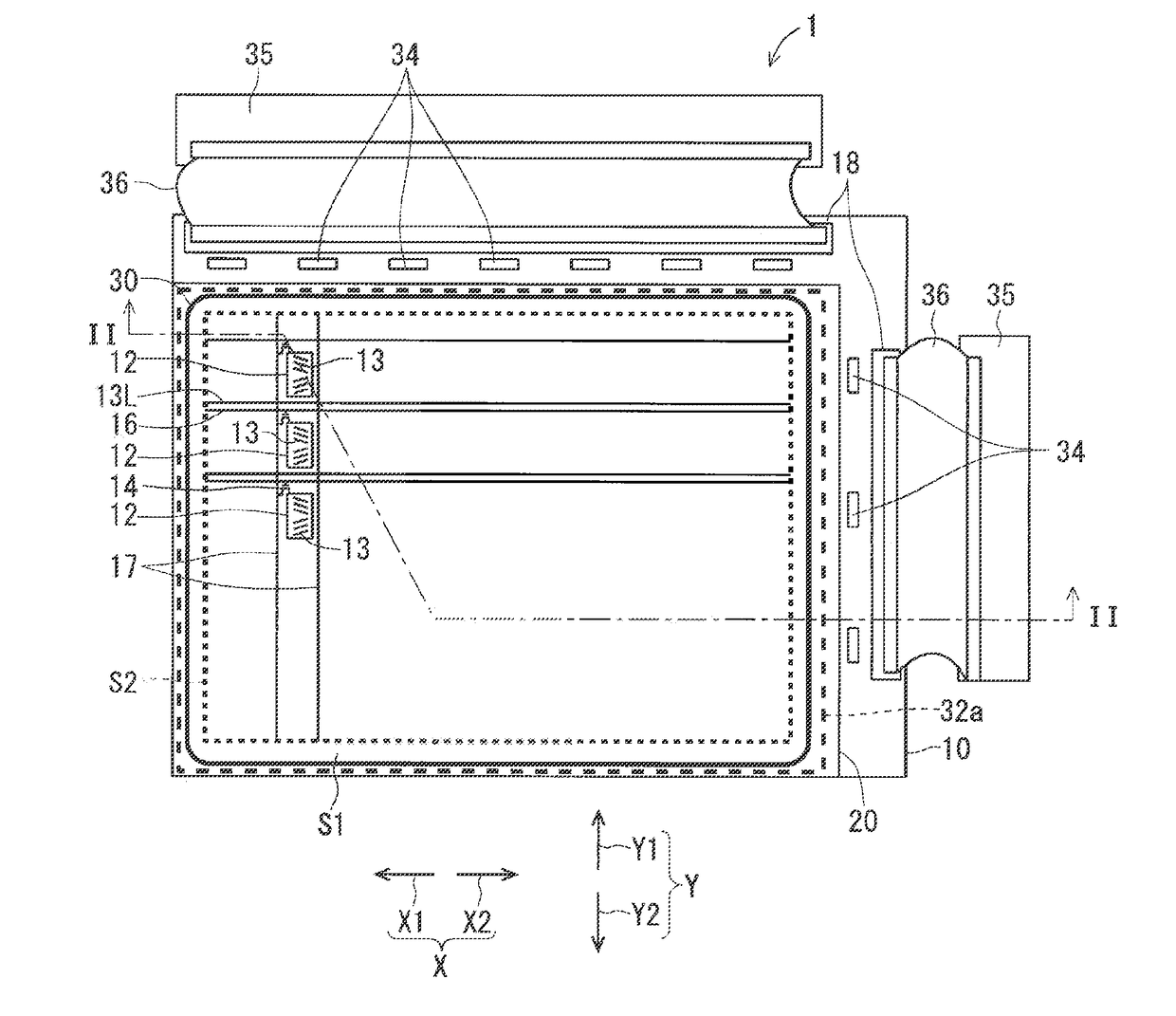
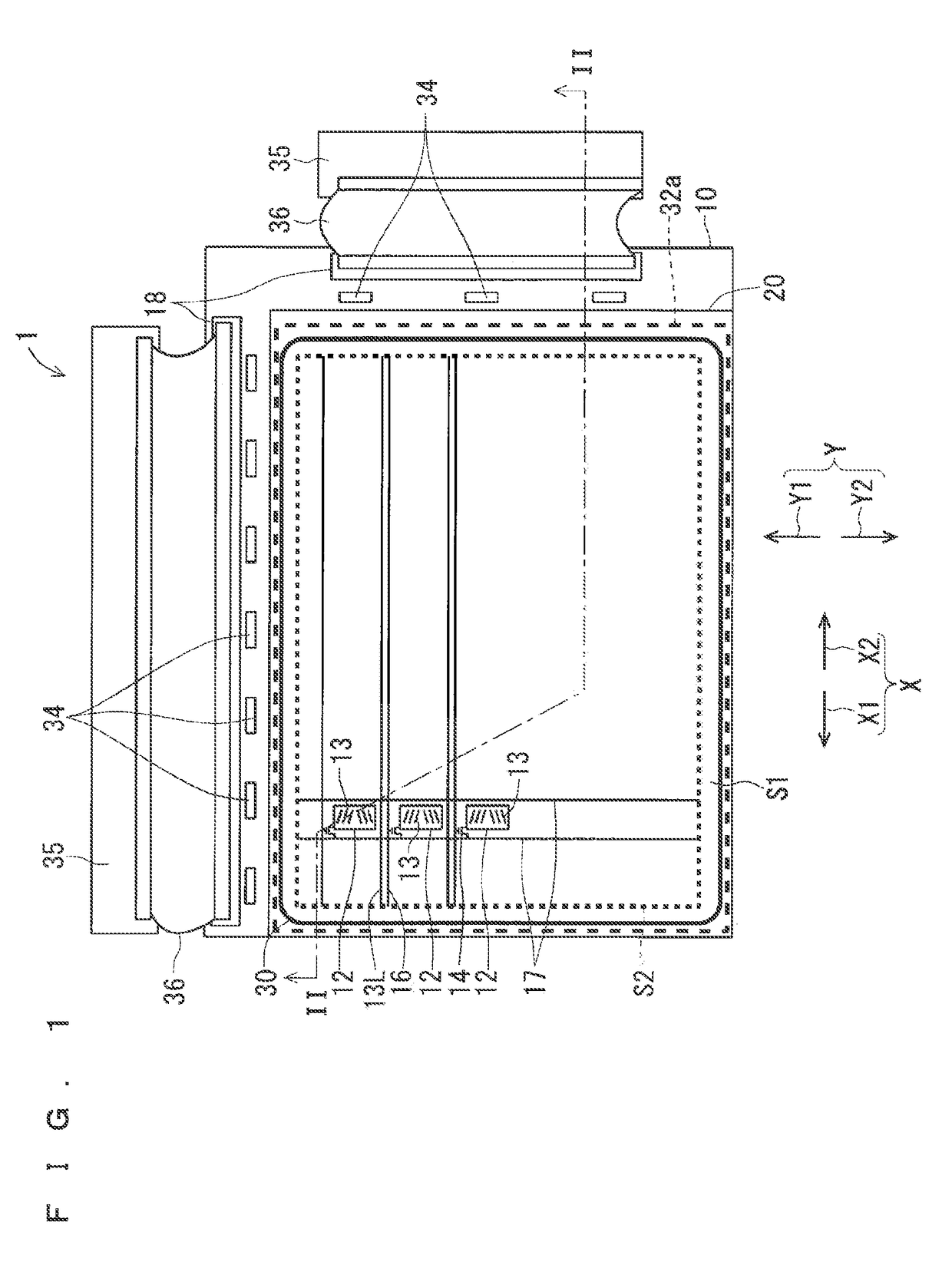
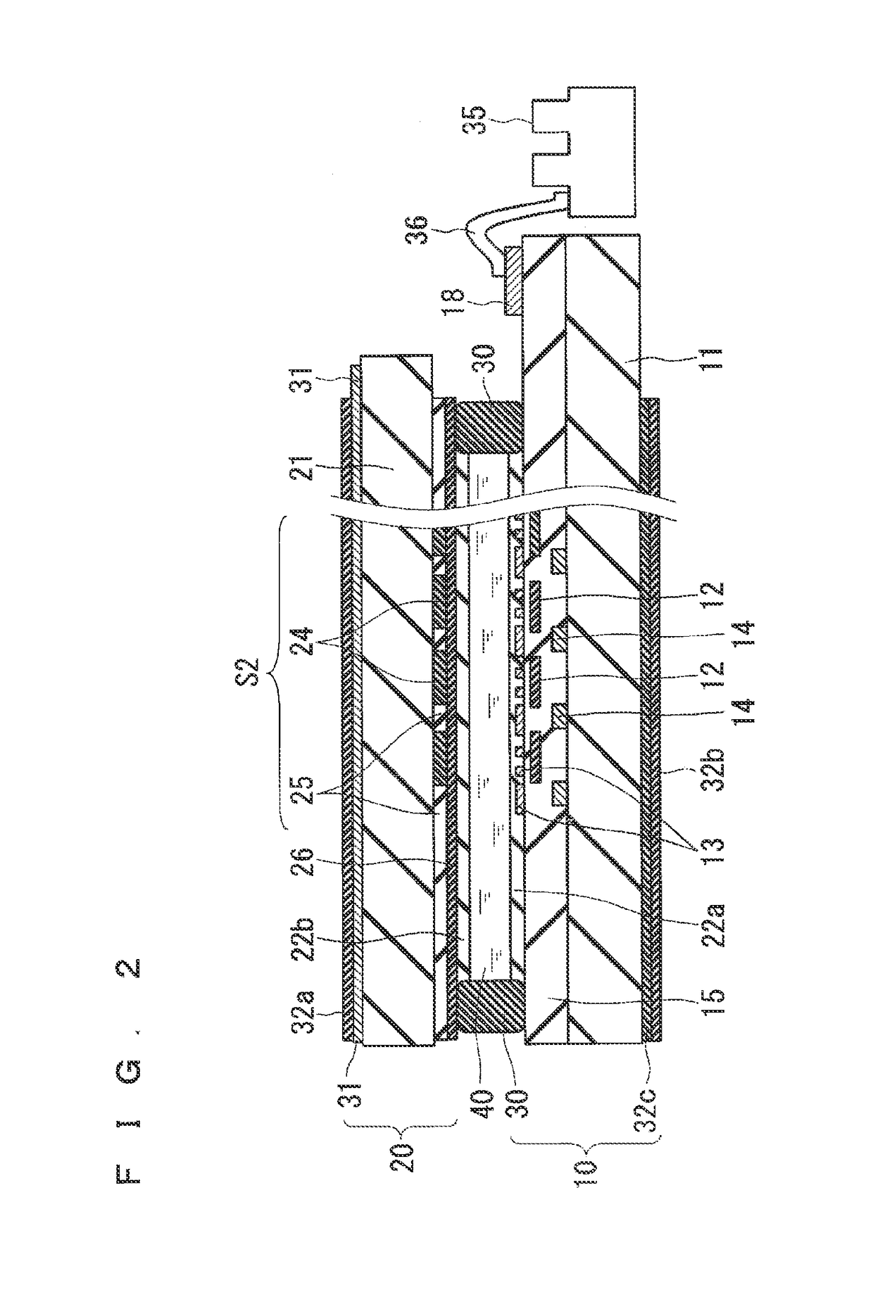
[0064]FIG. 1 is a plan view showing the structure of a liquid crystal panel 1 provided in a liquid crystal display device according to a first preferred embodiment of the present invention. FIG. 2 is a sectional view of the liquid crystal panel 1 as viewed from a cutting plane line II-II of FIG. 1.

[0065]The liquid crystal panel 1 shown as an example in FIGS. 1 and 2 adopts an in-plane system operated by using a thin film transistor (abbreviated as TFT) as a switching element. The liquid crystal panel 1 is more specifically a liquid crystal panel adopting a fringe field switching (FFS) system.

[0066]As shown in FIGS. 1 and 2, the liquid crystal panel 1 includes a TFT array substrate (simply called an “array substrate” in some cases) 10, a color filter substrate 20, and a seal material 30.

[0067]Both the array substrate 10 and the color filter substrate 20 are quadrilateral, more specifically rectangular in outer shape. In the first preferred embodiment, the outer shape of the array sub...


PUM

PropertyMeasurementUnit
angleaaaaaaaaaa
angleaaaaaaaaaa
twist angleaaaaaaaaaa

Abstract

A pretilt angle of a liquid crystal molecule on the side of an array substrate is formed such that the liquid crystal molecule goes away from the array substrate in a direction to the left when viewed from a position facing a display surface of a liquid crystal panel. The pretilt angle on the side of a counter substrate is formed such that the liquid crystal molecule goes away from the counter substrate in a direction to the right when viewed from a position facing the display surface. The directions to the left and the right define a direction X corresponding to a horizontal direction of the liquid crystal panel. A direction of a delay phase axis of a biaxial phase difference film is arranged in a position rotated anticlockwise in an angular range from over 0° to 1° from the direction X.

Description

BACKGROUND OF THE INVENTION[0001]Field of the Invention[0002]The present invention relates to a liquid crystal panel, a liquid crystal display device including the liquid crystal panel, and a method of manufacturing the liquid crystal panel.[0003]Description of the Background Art[0004]A liquid crystal display device is used for example as a display device of a car navigation system to be installed on a vehicle, for example. The liquid crystal display device installed on a vehicle is viewed from a driver's seat or a front passenger's seat, so that it is inevitably viewed from above. Thus, regarding the liquid crystal display device to be installed on a vehicle, adjusting a viewing angle range is required so as to optimize optical characteristics such as contrast characteristics when the liquid crystal display device is viewed from above.[0005]A technique of adjusting a viewing angle of a liquid crystal display device in a range preferable for a device to be installed on a vehicle is ...

Claims


Application Information

Patent Timeline
Patent Type & Authority Patents(United States)
IPC IPC(8): G02F1/1343G02F1/1333G02F1/1335H01L27/12G02F1/1368G02F1/139G02F1/13363G02F1/1337
CPCG02F1/1393G02F1/133634G02F1/133707G02F2001/134372G02F2001/133749G02F2001/133773G02F2001/133531G02F1/133528G02F1/13363G02F1/134309G02F1/134372G02F1/133531G02F1/133749G02F1/133773
Inventor YONEMURA, KOJIUMEDA, HIROSHIOKUMOTO, KAZUNORI
Owner TRIVALE TECH
Why Eureka
Try Eureka