Liquid crystal display device

a liquid crystal display and display device technology, applied in liquid crystal compositions, instruments, chemistry apparatus and processes, etc., can solve the problems of increasing oblique light leakage, only a remarkably poorer polarization degree with respect to light incoming from a oblique direction, etc., to achieve the effect of suppressing light leakage and preferable viewing angle characteristics

Active Publication Date: 2010-09-30
PANASONIC LIQUID CRYSTAL DISPLAY CO LTD +1
View PDF5 Cites 11 Cited by
  • Summary
  • Abstract
  • Description
  • Claims
  • Application Information

AI Technical Summary

Benefits of technology

[0031]According to the present invention, it is possible to provide a liquid crystal display device capable of suppressing light leakage in a oblique direction in a black state and having preferable viewing angle characteristics.

Problems solved by technology

However, the above described polarizing plate generally presents a high polarization degree only with respect to a vertical direction with respect to a plane viewed by an observer, that is, only when a light is incoming perpendicular to the plane, but presents only a remarkably poorer polarization degree with respect to a light incoming from a oblique direction.
In a liquid crystal display device, as light is incoming from the light source unit (back light) to the lower polarizing plate of the liquid crystal panel at all azimutal angles and substantially all polar angles, degradation of a polarization degree of a light incoming from a oblique direction may cause increase of oblique light leakage.

Method used


Image

  • Liquid crystal display device
  • Liquid crystal display device
  • Liquid crystal display device

Examples


first example

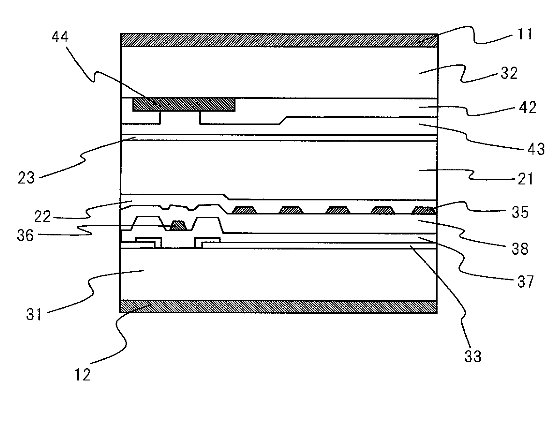
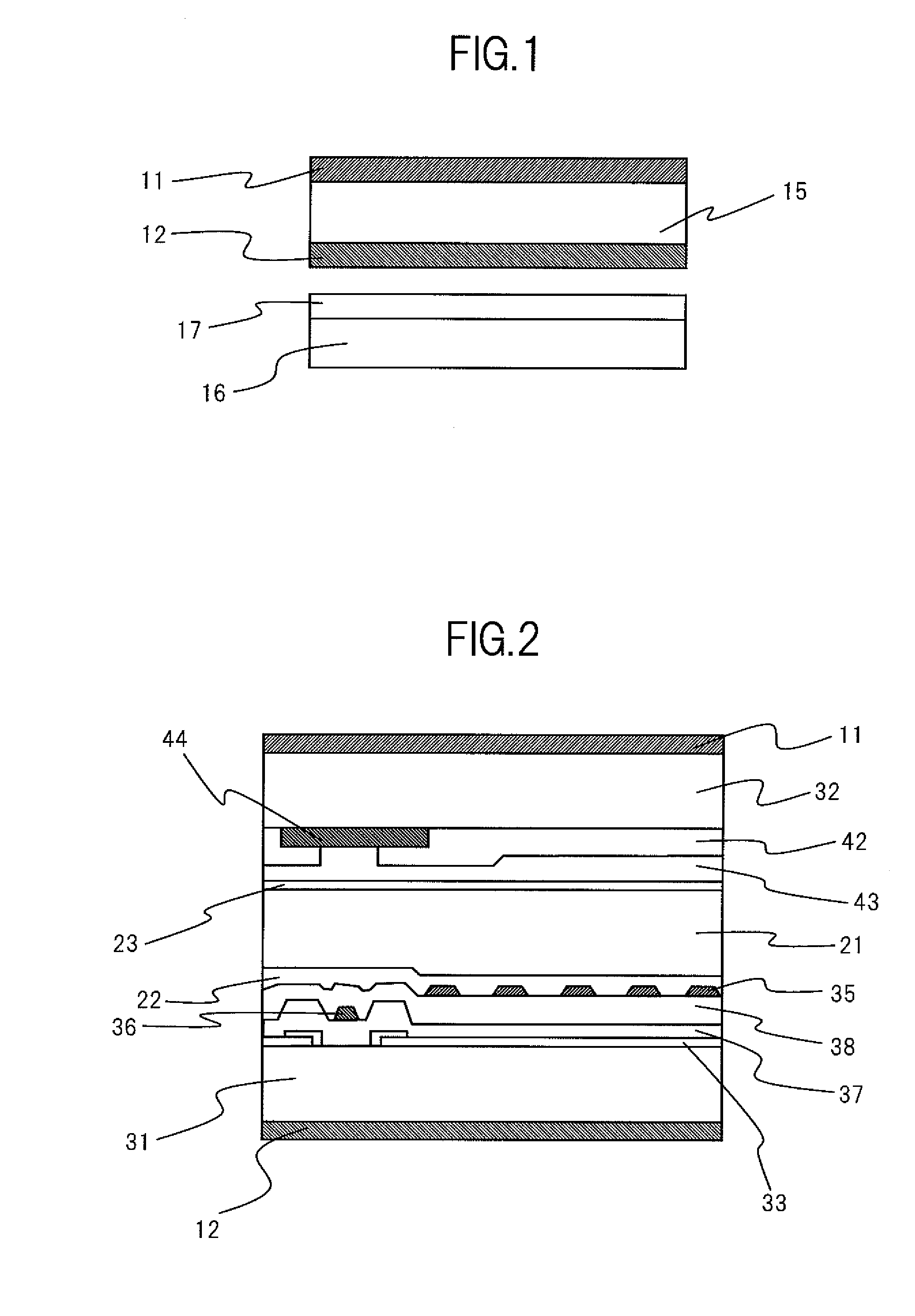
[0100]In the first example, nematic liquid crystal composite having a nematic-liquid phase transition temperature being 368 K, anisotropy of refractive index being 0.085 (wavelength 546 nm, 373 K) K1 being 9.9×10⁻¹²N, K2 being 7.2×10⁻¹²N, and K3 being 15.8×10⁻¹² N is enclosed in the liquid crystal cell 15 of a liquid crystal display device according to the above described embodiment.

[0101]A panel contrast ratio of a liquid crystal display device in the first example is 1520; and a contrast ratio for a direction at an in-plane azimutal angle of a polarization axis being 45 degrees and a polar angle being 45 degrees is 170.

[0102]Note that a panel contrast ratio (a front contrast ratio) is defined as a contrast ratio unique to a liquid crystal panel, which is defined based on the minimum luminance and maximum luminance with respect to an identical light source intensity without light modulation by a backlight source. In measurement, a value is obtained by dividing the maximum luminance...

second example

[0103]In the second example, nematic liquid crystal composite having anisotropy of refractive index being 0.084 (wavelength 546 phase, 313 K), K1 being 9.2×10⁻¹²N, K2 being 6.7×10⁻¹²N, and K3 being 17.4×10⁻¹² N, and a nematic-liquid phase transition temperature being 384 K is enclosed in the liquid crystal cell 15 of a liquid crystal display device according to the above described embodiment.

[0104]A front contrast ratio in the second example is 1610; and a contrast ratio for a direction at the azimuthal angle and the polar angle both being 45 degrees (φ=θ=45°) is 200.

third example

[0105]In the third example, nematic liquid crystal composite having anisotropy of refractive index being 0.091 (wavelength 546 nm, 313 K), K1 being 9.8×10⁻¹²N, K2 being 7.8×10⁻¹²N, and K3 being 17.6×10¹² N, and a nematic-liquid phase transition temperature being 390 K is enclosed in the liquid crystal cell 15 of a liquid crystal display device according to the above described embodiment.

[0106]A front contrast ratio in the third example is 1800; and a contract ratio for a direction at the azimutal angle and the polar angle both being 45 degrees is 210.


PUM

PropertyMeasurementUnit
polar angleaaaaaaaaaa
refractive indexaaaaaaaaaa

Abstract

A liquid crystal display device comprising a liquid crystal panel having a cell 15 and polarizing plates 11, 12; wherein a liquid crystal molecule is rotated in parallel to the cell 15, the polarizing plate 12 has a multiple polarizer layer formed thereon, the multiple player having a first polarizer layer having a higher polarization degree with respect to a light from a forward direction than a polarization degree with respect to a light from a oblique direction and a second polarizer layer having a higher polarization degree with respect to a light from a oblique direction than a polarization degree with respect to a light from a forward direction, and an average elastic constant of a splay elastic constant K1, a twist elastic constant K2, and a bend elastic constant K3 of liquid crystal material is equal to 10×10−12 N or larger and satisfies a relationship of K1/K2<=1.5.

Description

CROSS-REFERENCE TO RELATED APPLICATION[0001]The present application claims priority from Japanese application JP2009-075421 filed on Mar. 26, 2009, the content of which is hereby incorporated by reference into this application.BACKGROUND OF THE INVENTION[0002]1. Field of the Invention[0003]The present invention relates to a liquid crystal display device having wide viewing angle characteristics and high performance of image quality capable of maintaining a high contrast ratio.[0004]2. Description of the Related Art[0005]A liquid crystal display has a strength, compared to a CRT (Cathode Ray Tube, generally referred to as CRT), or a conventional mainstream of display devices, in that the display device can be formed thin and light. As development of a technique for improving image quality, use and market for liquid crystal displays have been expanded.[0006]In recent years, for example, a monitor of a desk top personal computer or for printing or designing, use of a liquid crystal tel...

Claims


Application Information

Patent Timeline
Patent Type & Authority Applications(United States)
IPC IPC(8): G02F1/1335
CPCG02F1/133528G02F1/13363G02F2413/02G02F2001/133635G02F1/133634G02F1/133635
Inventor UTSUMI, YUKATAKEDA, SHINTAROHIYAMA, IKUOONO, KIKUO
Owner PANASONIC LIQUID CRYSTAL DISPLAY CO LTD
Why Eureka
Try Eureka