
System and method for transcoding with adaptive bit rate control

Inactive Publication Date: 2005-03-17
SHARP KK
View PDF6 Cites 43 Cited by
  • Summary
  • Abstract
  • Description
  • Claims
  • Application Information

AI Technical Summary

Benefits of technology

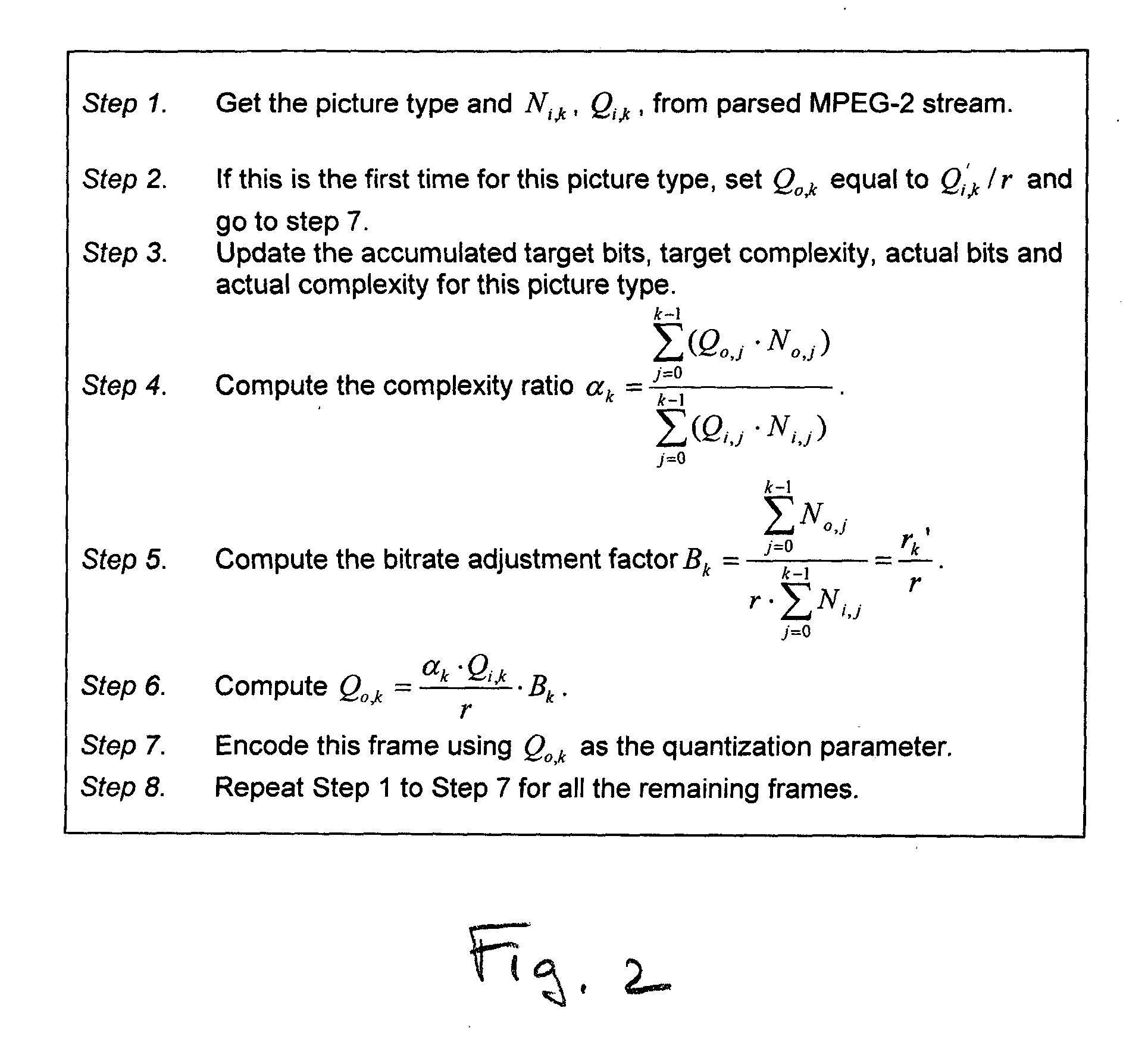
The scale factor consists of two parts: one is the complexity ratio information between the actual (current) output complexity and the input complexity; the other is the bitrate correction factor based on the ratio of the actual bits produced verses the target bits. Both factors are adaptively adjusted over the encoding process. Separate rate controls are performed for different picture types (I, P, and B). In this manner, the bit allocation among different picture types tracks the allocation in the input MPEG-2 stream. By using this rate control method, the encoder can meet the bitrate target very closely and achieve an overall better visual quality than using the internal (conventional) MPEG-4 rate control.

Problems solved by technology

This is not optimal for the overall bit allocation.
This operation wastes time, thereby causing the delay in the transcoding process.
However, the de-quantizer must wait until the decoding process of the picture has been completed over the entire target transcoding frame, thereby causing the delay in the transcoding process.
The third conventional transcoder, however, has another problem.
The encoder that is linked with the third transcoder must provide the above information on the number of coding bits to be recorded in the bit streams, thereby causing the delay of process in the encoder.
However, this solution does not work well if the group of pictures structure of the bitstream changes.
In such a case, the extrapolation of picture coding type will be erroneous.
In the example above, the unanticipated rise in I picture frequency will result in an incorrect allocation of bits and degraded quality for unanticipated I pictures.
However, this solution does not work well if the bit rate of the originally encoded bitstream fed to the transcoder is far higher than the bit rate of the re-encoded bitstream produced by the transcoder.

Method used


Image

  • System and method for transcoding with adaptive bit rate control
  • System and method for transcoding with adaptive bit rate control
  • System and method for transcoding with adaptive bit rate control

Examples


Embodiment Construction

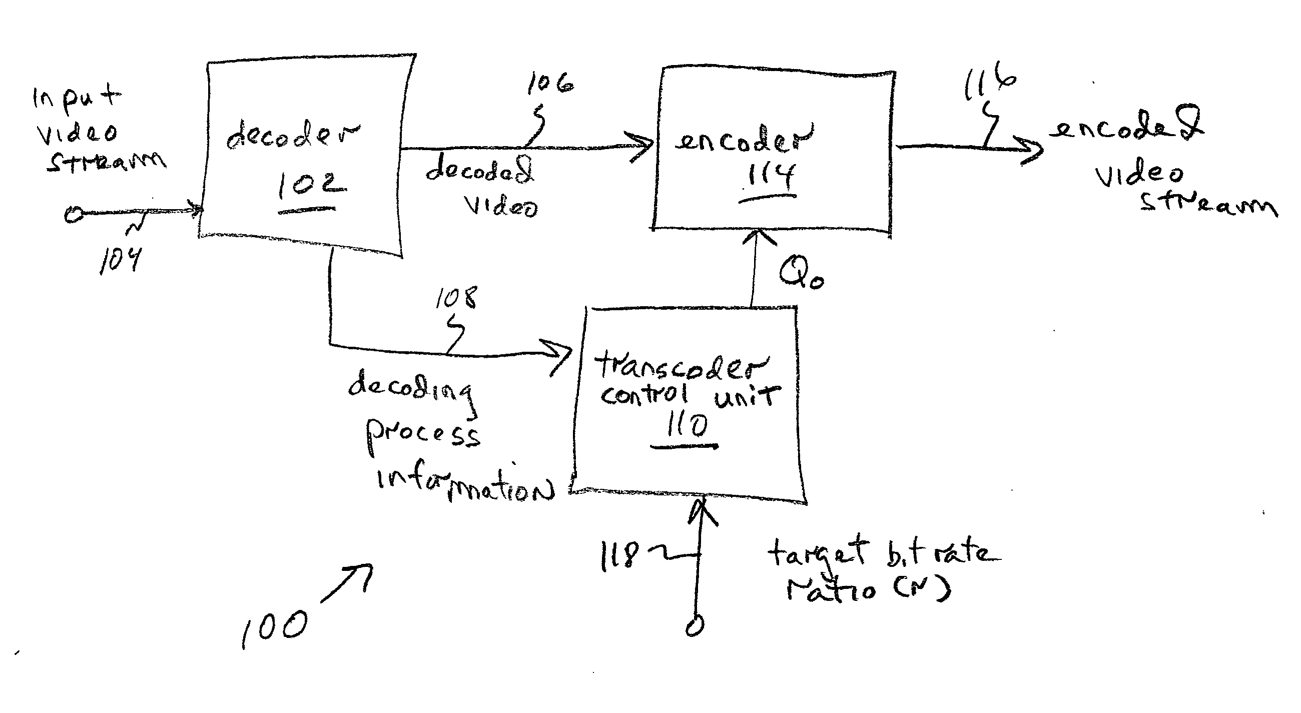
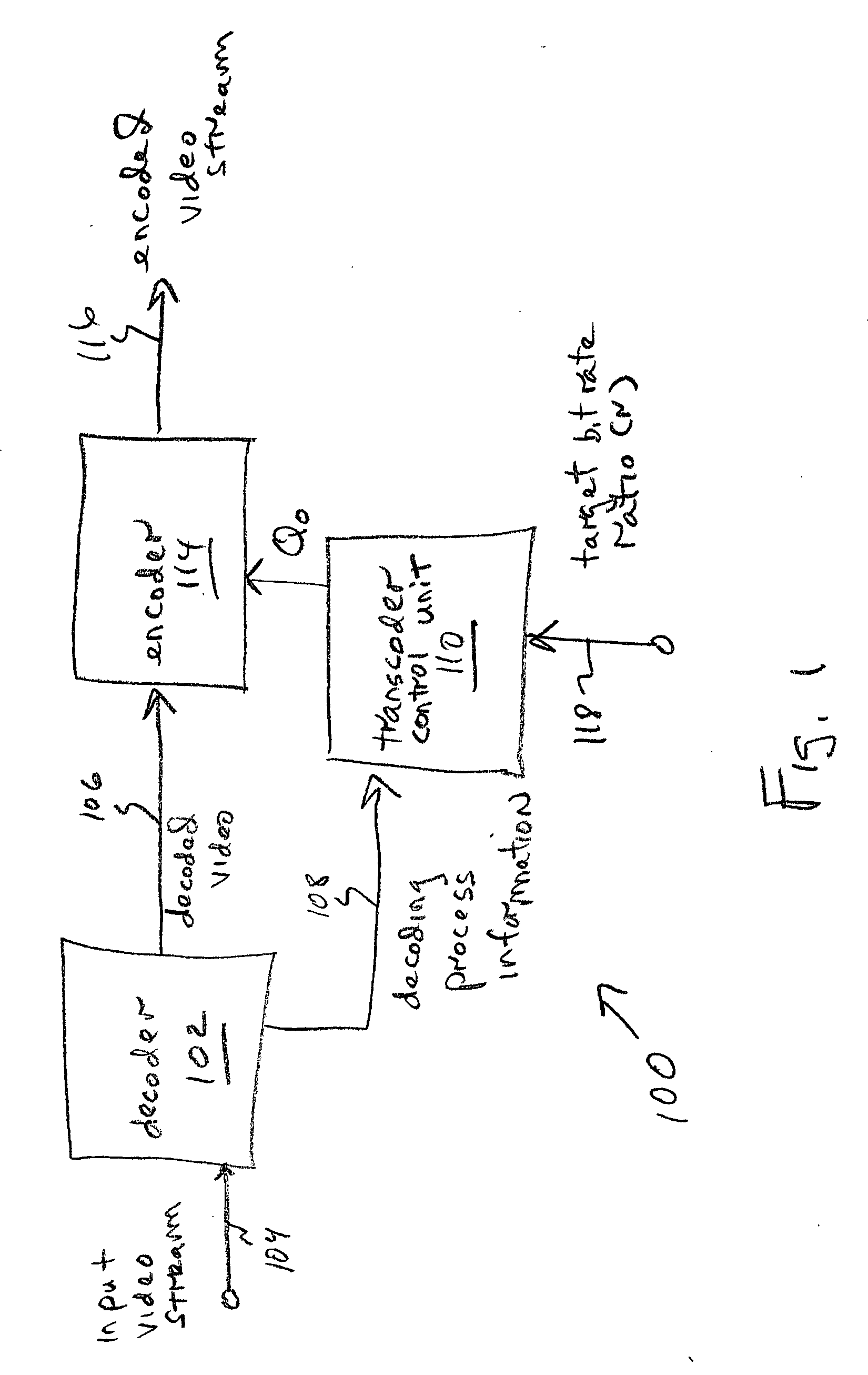
FIG. 1 is a schematic block diagram of the present invention system for adaptive rate control in the transcoding of video streams. The system 100 comprises a decoder 102 having an interface on line 104 to accept frames of an input MPEG encoded video stream and an interface on line 106 to supply a decoded video stream. The decoder 102 has an interface on line 108 to supply decoding process information.

A transcoder control unit 110 has an interface on line 108 to accept the decoding process information. The transcoder control unit 110 determines video stream complexity and supplies an output video stream quantization parameter (Qo) on line 112 that is responsive to determined video stream complexity for each frame of the decoded video stream. An encoder 114 has an interface on line 106 to accept the decoded video and an interface on line 112 to accept Qo. The encoder 114 has an interface on line 116 to supply an output video stream encoded into a protocol using Qo. Typically, the out...


PUM


Abstract

A system and method are provided for adaptive rate control in the transcoding of video streams. The method comprises: accepting frames of an input MPEG encoded video stream; decoding the video stream; determining video stream complexity; for each frame, calculating an output video stream quantization parameter (Qo) responsive to determined video stream complexity; and, encoding the output video stream into a protocol using Qo. Some aspects further comprise accepting a target bit rate ratio (r) for transcoding that is equal to the ratio of the target output video stream number of bits per frame (No), to the input video stream number of bits per frame (Ni). Then, Qo is also calculated in response to the value of r. More explicitly, Qo is calculated in response to a complexity ratio of: an accumulated complexity in the output video stream, to an accumulated complexity in the input video stream.

Description

BACKGROUND OF THE INVENTION 1. Field of the Invention This invention generally relates to digital image communication processes and, more particularly, to a system and method for adaptively controlling the bit rate, when transcoding between compressed video protocols. 2. Description of the Related Art Compressed digital video is widely used in multimedia applications. There exist many digital video coding standards. Different applications and environments have different video stream requirements. Therefore, the conversion of digital video bitstreams from one compressed format, into another, is necessary. This process is called video transcoding. The format change may be a different bitrate, frame size, or even compression standard. The conventional rate control method uses a one-pass process. With conventional rate control, the encoder makes assumptions concerning the picture types, without knowledge of the sequence. It controls bit allocations and quantization based on the pic...

Claims


Application Information

Patent Timeline
IPC IPC(8): H04N7/26H04N7/50
CPCH04N19/172H04N19/149H04N19/15H04N19/40H04N19/124H04N19/14H04N19/152H04N19/61
Inventor ZHAO, JIESUN, SHIJUN
Owner SHARP KK
Learn More