Method and apparatus for detecting a workpiece, and method and apparatus for inspecting a workpiece

a technology for workpieces and inspection methods, applied in the direction of instruments, vehicle tyre testing, structural/machine measurement, etc., can solve the problems of difficult optical alignment of line portions, inability to judge the shape of workpieces accurately, and bulky apparatus

Inactive Publication Date: 2005-03-17
MICRON TECH INC +1
View PDF4 Cites 58 Cited by
  • Summary
  • Abstract
  • Description
  • Claims
  • Application Information

AI Technical Summary

Problems solved by technology

However, discoloration or stains can be judged accurately from data on the appearance imaged by the line camera but the shape of the workpiece cannot be judged accurately.
However, in the above method, the apparatus becomes bulky and it is difficult to optically align a line portion to be imaged by the line camera 52 with a line portion to be imaged by the area camera 55.
Although it is possible to align the obtained two images by software, data processing becomes complicated and storage means or computing means for processing data is necessary.

Method used


Image

  • Method and apparatus for detecting a workpiece, and method and apparatus for inspecting a workpiece
  • Method and apparatus for detecting a workpiece, and method and apparatus for inspecting a workpiece
  • Method and apparatus for detecting a workpiece, and method and apparatus for inspecting a workpiece

Examples


Embodiment Construction

[0039] Preferred embodiments of the present invention will be described hereinbelow with reference to the accompanying drawings.

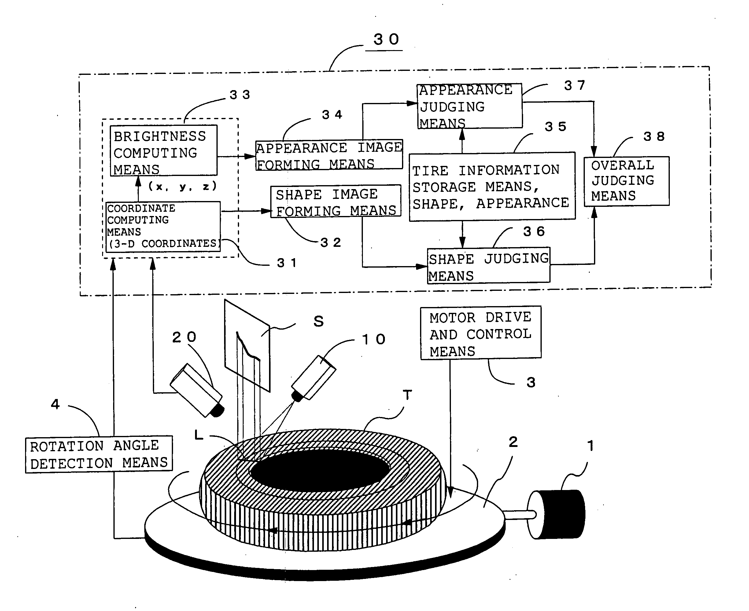
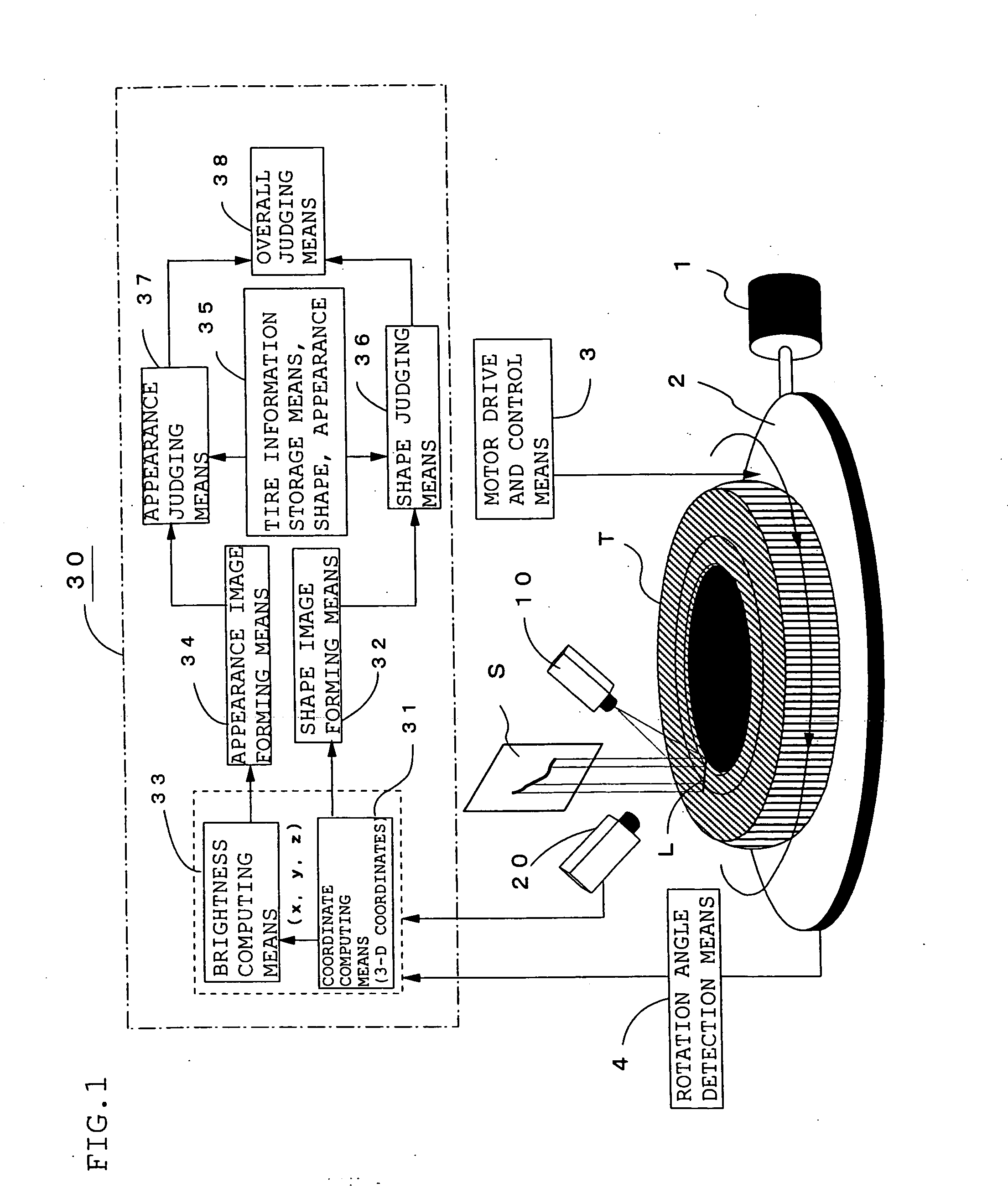
[0040]FIG. 1 is a diagram showing the constitution of a tire appearance and shape inspection apparatus according to a preferred embodiment of the present invention. In FIG. 1, reference numeral 10 denotes floodlight means for applying white slit light to the surface to be inspected of a tire T as a workpiece mounted on a rotary table 2 turned by a motor 1, 20 a color CCD camera, having pixels on a plane, for imaging a portion L illuminated by the above slit light of the turning tire T, 30 a tire judging unit for judging whether the shape and appearance of the above tire are acceptable or not by detecting the shape and appearance of the tire T from an image obtained by the color CCD camera 20, 3 motor drive and control means for driving and controlling the above motor 1, and 4 rotation angle detection means for detecting the rotation angle θ of the tire T b...


PUM


Abstract

A tire T as a workpiece mounted on a rotary table 2 is imaged by using floodlight means 10 for applying white slit light and a color CCD camera 20 for imaging a portion illuminated by the slit light while it is turned, the coordinates and brightness of the tire T are detected from the obtained image data by coordinate computing means 31 and brightness computing means 33, and the 3-D coordinate data and color image of the tire T are re-formed from the obtained shape data and brightness data of the tire T by shape image forming means 32 and appearance image forming means 34 and compared with tire appearance and shape data prestored in tire information storage means 35 to judge whether the appearance and shape of the tire T are acceptable or not.

Description

BACKGROUND OF THE INVENTION [0001] 1. Field of the Invention [0002] The present invention relates to a method and apparatus for detecting or inspecting the appearance and shape of a workpiece such as a tire or tire part by imaging it. [0003] 2. Description of the Prior Art [0004] In the prior art, as one of product inspection methods, a product is imaged by a line camera to judge whether the surface state such as discoloration or stains of the workpiece is acceptable or not from the obtained appearance data. However, discoloration or stains can be judged accurately from data on the appearance imaged by the line camera but the shape of the workpiece cannot be judged accurately. Therefore, a light-section method in which the surface of the workpiece is imaged by an area camera by applying slit light to detect the shape of the workpiece from the obtained image data is employed. [0005] To inspect the shape of a tire by the above light-section method, as disclosed by JP-A 11-138654 (the ...

Claims


Application Information

Patent Timeline
Patent Type & Authority Applications(United States)
IPC IPC(8): G01B11/30G01B11/24G01B11/25G01M17/02
CPCG01B11/24G01B11/2522G06T7/0057G01N21/8851G01N21/95G01M17/027G06T7/521
Inventor KANEKO, TOMOYUKIKOKUBU, TAKAO
Owner MICRON TECH INC
Why Eureka
Try Eureka