System and method for frequency translation with harmonic suppression using mixer stages

a technology of harmonic suppression and mixer stage, applied in the field of circuits, can solve the problems of inability to implement suitable pre-select filter, inapplicability of ideal multiplier, and difficulty or inability to achieve suitable pre-select filter implementation with current ic technology, and achieve the effect of substantially reducing the disadvantages and eliminating the problems associated with prior frequency translation circuits

Inactive Publication Date: 2005-03-17
CSR TECH INC
View PDF31 Cites 52 Cited by
  • Summary
  • Abstract
  • Description
  • Claims
  • Application Information

AI Technical Summary

Benefits of technology

In accordance with the present invention, the disadvantages and problems associated wi

Problems solved by technology

Unfortunately, ideal multipliers are not practical for a variety of reasons.
Unfortunately, a

Method used


Image

  • System and method for frequency translation with harmonic suppression using mixer stages
  • System and method for frequency translation with harmonic suppression using mixer stages
  • System and method for frequency translation with harmonic suppression using mixer stages

Examples


Embodiment Construction

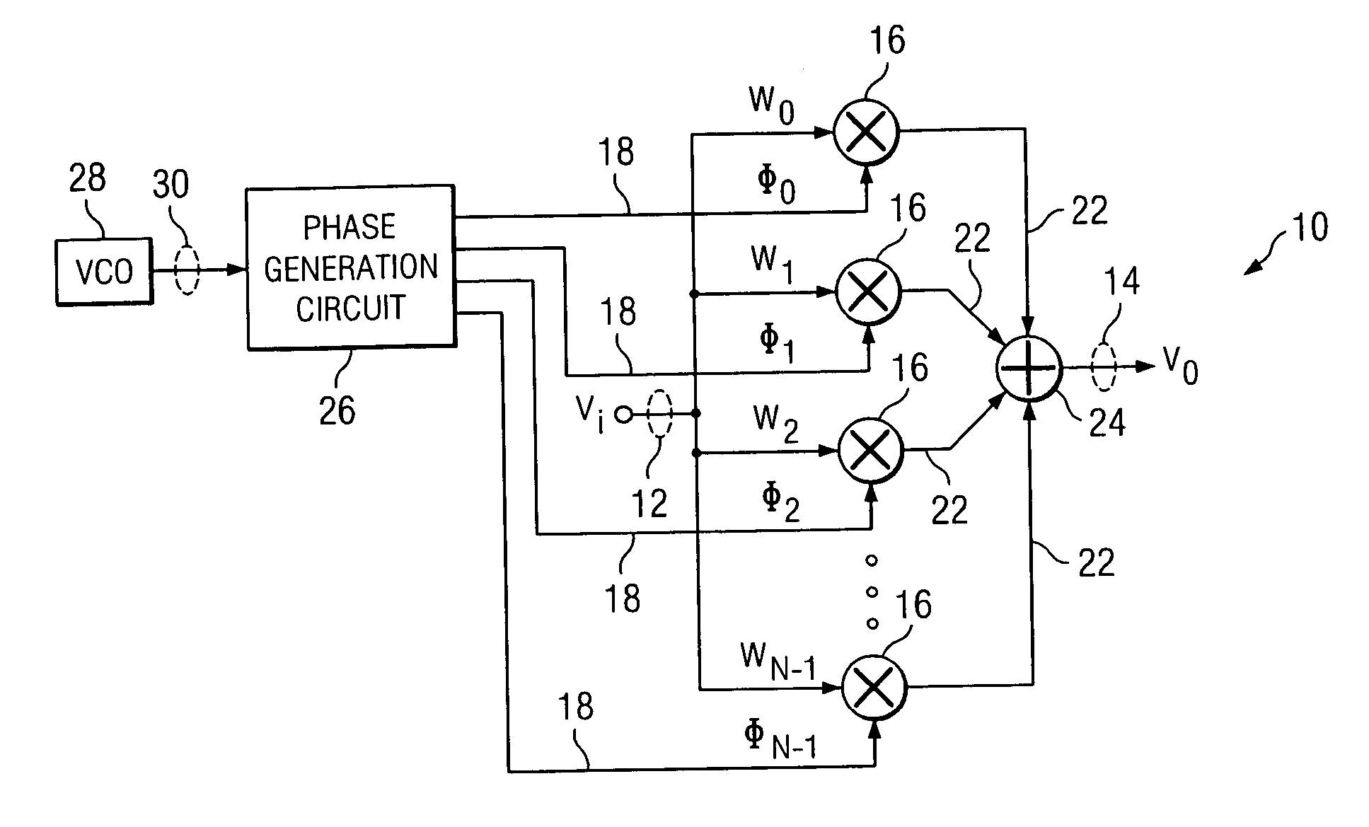
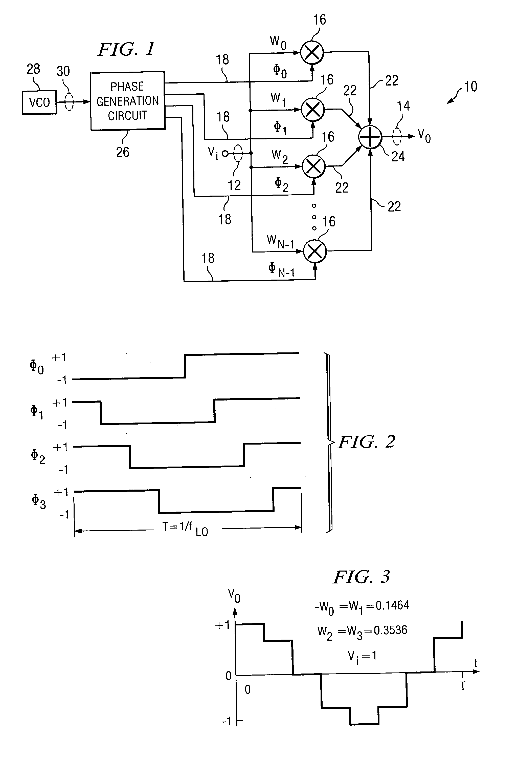
FIG. 1 illustrates one embodiment of a circuit 10 for suppressing the harmonics of a radio frequency (RF) signal 12 to be frequency translated (e.g., down-converted or up-converted) to an intermediate frequency (IF) signal 14. Circuit 10 comprises an array of N mixers 16 to approximate the multiplication of RF signal 12 by an ideal sine-wave. Each mixer 16 multiplies the RF signal 12 by a phase signal 18 having a magnitude of, for example, either plus or minus one. The RF signal 12 is weighted according to a weighting factor (e.g., multiplied by wi) before the input to each mixer 16. All mixer outputs 22 are summed by a summing circuit 24 to generate the IF signal 14.

In a television system, signals representing individual channels are assigned to specific frequencies in a defined frequency band. For example, in the United States, television signals are generally transmitted in a band from 48 MHz to 852 MHz. In such television systems, RF signal 12 comprises a radio frequency signal...


PUM


Abstract

A circuit for frequency translating a radio frequency signal comprises a plurality of mixer stages, each stage associated with a particular range of frequencies of a radio frequency signal. The circuit further comprises a switching circuit that communicates the radio frequency signal to a selected one of the plurality of mixer stages in response to a control signal. The selected mixer stage comprises a phase generation circuit that generates a plurality of phase signals, and at least one mixer that combines the radio frequency signal with one of the plurality of phase signals to generate at least a portion of an intermediate frequency signal.

Description

TECHNICAL FIELD OF THE INVENTION This invention relates to circuits and more particularly to frequency translation with harmonic suppression using mixer stages. BACKGROUND OF THE INVENTION Mixers are the circuit blocks of a communication system that perform frequency translation of the carrier signals. Mixers are therefore used to frequency translate a desired radio frequency (RF) signal from a broadband signal to an intermediate frequency (IF) signal. Ideally, a frequency translation receiver, such as a direct down-conversion receiver, using a mixer multiplies the RF signal of interest by a pure sine wave, known as the local oscillator (LO) signal. This ideal multiplication produces signals only at the sum and difference of the RF and LO frequencies. With low pass filtering of the multiplier output, the receiver responds only to the signals at the frequency of interest, i.e. RF signals in a small band centered about the LO frequency. Unfortunately, ideal multipliers are not prac...

Claims


Application Information

Patent Timeline
IPC IPC(8): H03C3/40H03D7/16H04B1/10H04B1/18H04B1/26H04B15/00
CPCH03D7/00H03C3/40
Inventor DAVIS, THOMAS L.
Owner CSR TECH INC
Why Eureka
Try Eureka