Modular water play structure

Inactive Publication Date: 2005-03-17
UNKNOWN
View PDF89 Cites 67 Cited by
  • Summary
  • Abstract
  • Description
  • Claims
  • Application Information

AI Technical Summary

Benefits of technology

[0012] The present invention is designed to overcome the aforementioned problems and meet the aforementioned, and other, needs. It is one aspect of the present invention to provide a multi-level, water play structure that eliminates the need for various vertical support columns, which must be individually tailored to accommodate various collection basin environmental constraints. It is another aspect of the present invention to provide a water play structure that integrates a w

Problems solved by technology

Though many improvements have been made to water play structures over the years, there are still a number of problems which need to be addressed in such systems.
One such problem relates to quickly, efficiently, and uniformly installing the water play structures into collection basins of virtually any shape, size or configuration.
Tailoring each water play structure vertical support column to accommodate the slope of a particular grade is costly and inhibits mass production and uniform installation procedures.
Another problem with water play structures currently known in the art is that they utilize an independent conduit structure for transmitting pressurized water to the various water play elements disposed throughout the play structure.
As a result, as additional play levels, which include additional water play elements, are added to a particular play structure, additional conduit is needed to transmit the water supply to the added level, which can be costly.
Another problem with water play structures currently known in the art is that if a developer wants to link several water play structures together in a particular site, he or she must use multiple connections to a single water supply or use multiple water supplies.
However, these play elements, once installed, are not typically interchangeable or easily movable from one site on a play structure to another.
This limitation makes servicing the play elements difficult and restricts an operator's ability to manipulate or add new play elements to vary the play participants' recreational experience.

Method used


Image

  • Modular water play structure
  • Modular water play structure
  • Modular water play structure

Examples


Embodiment Construction

[0048] While this invention is susceptible of embodiments in many different forms, there are shown in the drawings and will herein be described in detail, preferred embodiments of the invention. The reader is to understand that the present disclosure is to be considered as an exemplification of the principles of the invention and is not intended to limit the broad aspects of the invention to the embodiments illustrated.

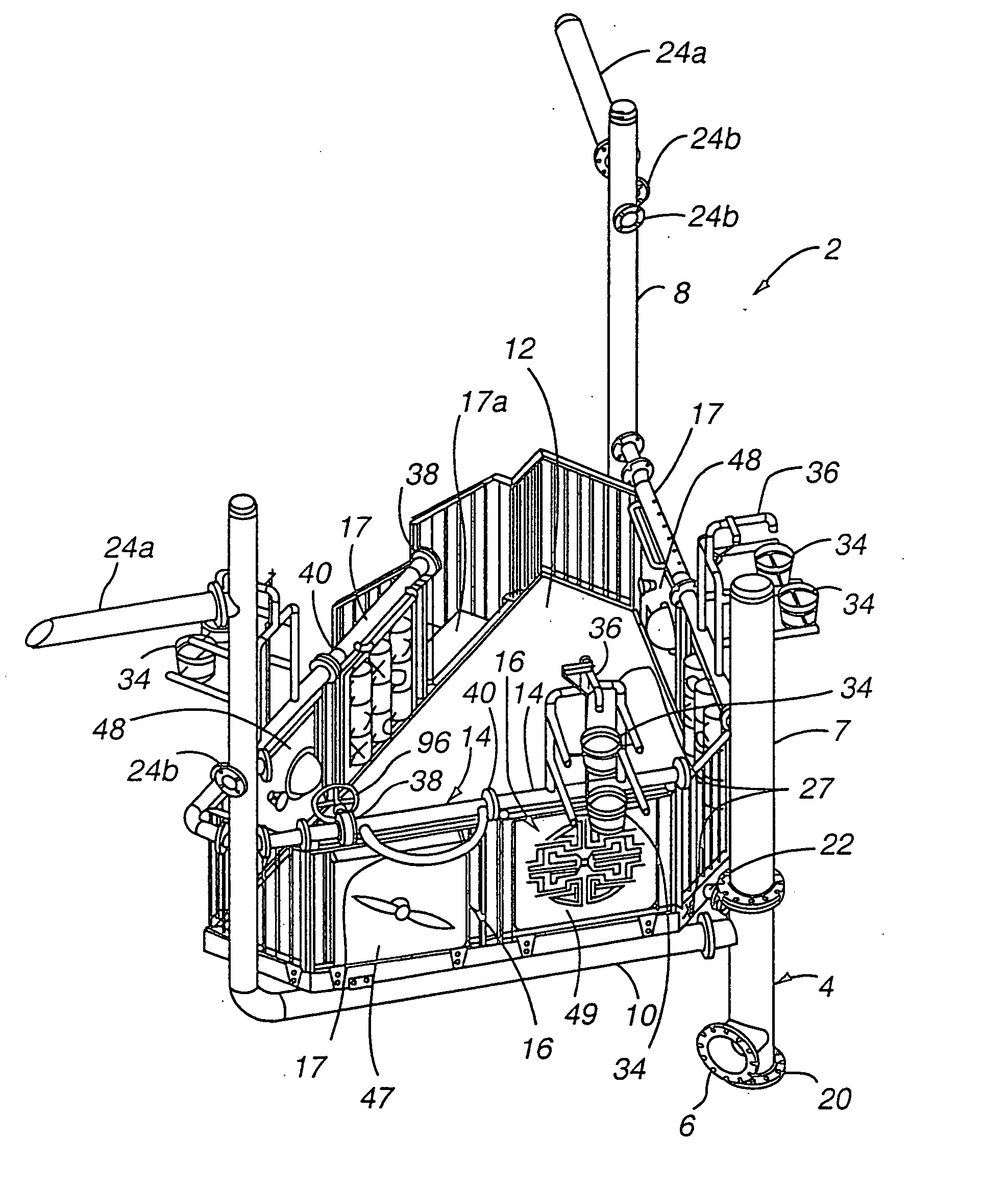
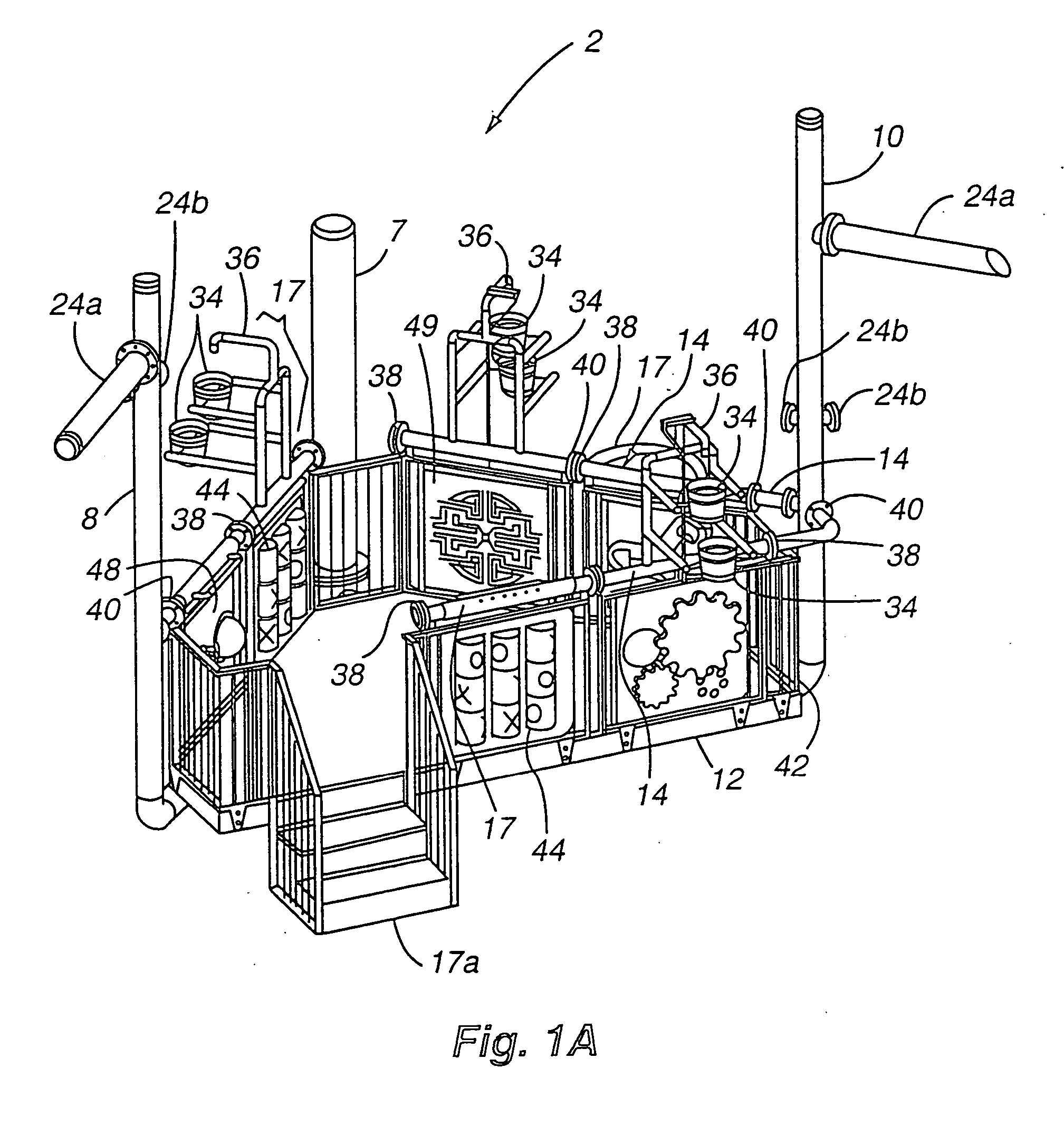
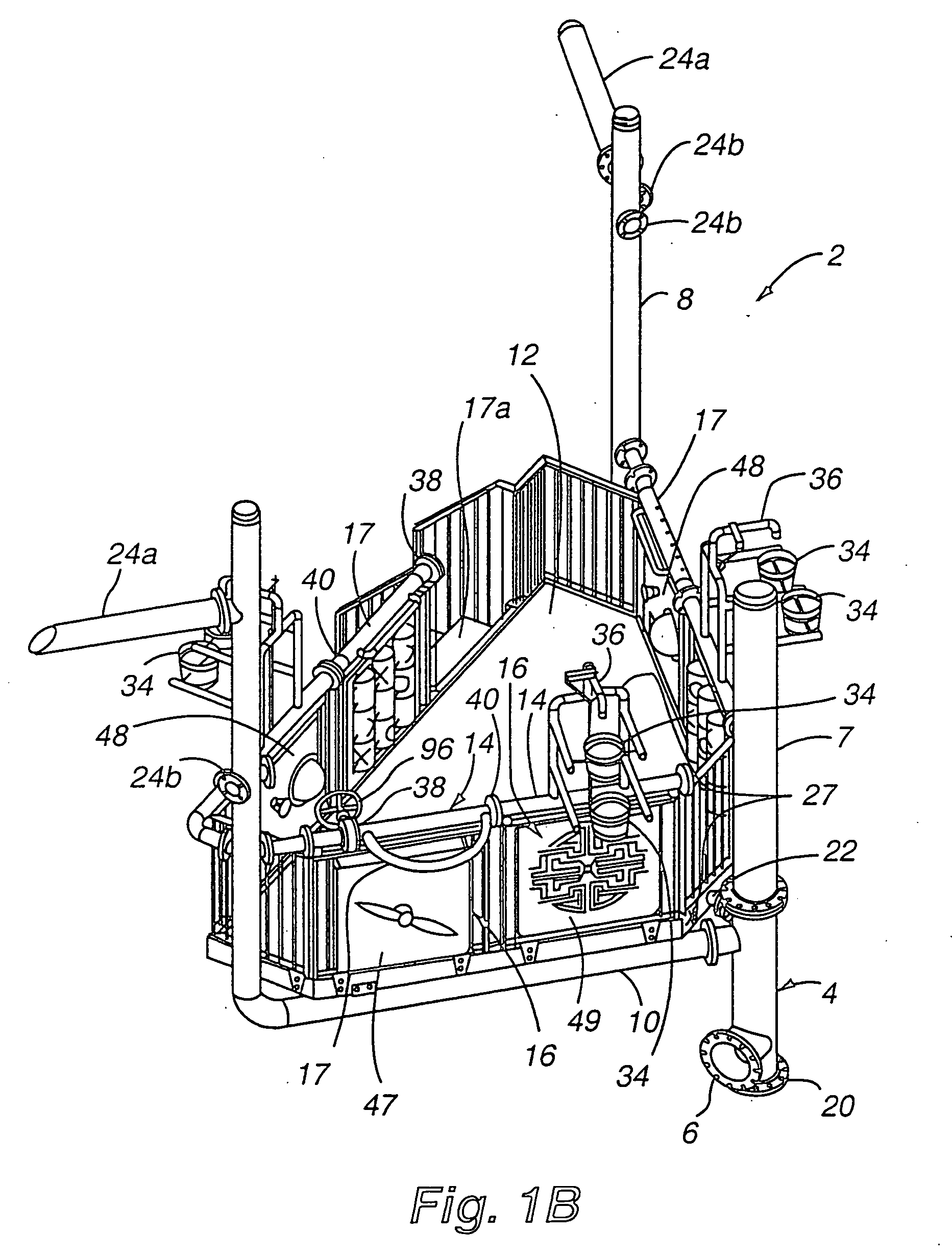
[0049] Referring now to the drawings, FIGS. 1A, 1B, and 1C illustrate front, side, and rear isometric views of one embodiment of the inventive modular water play structure 2, which can be easily adapted to a variety of sloped basins or pools 3 (shown in FIG. 2). In general, the modular water play structure 2 is comprised of a first central pedestal 4, which has a water supply line connection 6 for transmitting water from a water supply. The first central pedestal, in addition, has multiple other ports 23 that can be used to supply water to other areas of the water pl...


PUM


Abstract

An improved water play structure, which integrates a single water supply network of conduit with a central support infrastructure, is provided. In one embodiment, a plurality of central pedestals are interconnected to water supply legs in a staircase manner in order to deliver a single water supply to a plurality of interactive water play elements. The size of the water play structure can be increased to accommodate additional play participants by adding decks to the structure. Interactive play modules consisting of water play elements and interactive play apparatuses can be easily interchanged, which facilitates servicing, simplifies design and manufacturing, and adds variety to a play participant's recreational experience. In addition, multiple water play structures can be interconnected to each other without the need for establishing separate water supply line connections.

Description

[0001] This application is a continuation of U.S. patent application Ser. No. 10 / 199,396, filed Jul. 18, 2002, which claims the benefit of U.S. Provisional Application Ser. No. 60 / 392,949, filed Jun. 28, 2002, both applications being incorporated by reference herein in their entireties. Cross-reference is also made to U.S. Pat. No. 5,194,048, entitled “PARTICIPATORY WATER PLAY APPARATUS”, issued Mar. 16, 1993; U.S. Pat. No. 5,405,294, entitled “PARTICIPATORY WATER PLAY APPARATUS”, issued Apr. 11, 1995; U.S. Pat. No. 5,662,525, entitled “PARTICIPATORY WATER PLAY APPARATUS”, issued Sep. 2, 1997; and U.S. Pat. No. 5,820,471, entitled “PARTICIPATORY WATER PLAY SYSTEM”, issued Oct. 13, 1998, all of which are incorporated by reference herein in their entireties.FIELD OF THE INVENTION [0002] The present invention relates to the field of water play structures, and more particularly to a play system structure with a central pedestal that is pressurized by water. BACKGROUND OF THE INVENTION [...

Claims


Application Information

Patent Timeline
IPC IPC(8): A63B9/00A63B67/00
CPCA63B9/00A63B67/007A63G31/007A63B2208/12A63B2009/008A63G31/00
Inventor BRIGGS, RICK A.BROWN, CARIN R.MORAN, RICHARD T.
Owner UNKNOWN
Why Eureka
Try Eureka