Saw guide apparatus

a technology of guide apparatus and saw guide, which is applied in the direction of chain saws, metal sawing devices, manufacturing tools, etc., can solve the problems of difficulty in accurately guiding the saw as it is moved along the workpiece, large difficulty, and frequent encounter of longer workpieces

Inactive Publication Date: 2005-03-24
CUTTING EDGE INVENTIONS
View PDF9 Cites 29 Cited by
  • Summary
  • Abstract
  • Description
  • Claims
  • Application Information

AI Technical Summary

Benefits of technology

[0006] The track preferably is composed of multiple sections which may be coupled to one another in such manner as to form a track of such length as to span a workpiece having a length of up to eight or ten feet. The track forming members are clamped to the workpiece adjacent the ends of such members, thereby making it possible for the track to become laterally bowed between its ends in some instances. To overcome this undesirable characteristic apparatus according to the invention includes a stabilizing bar which may be coupled to a track-forming section in such manner as to prevent bowing of such section in either one of two opposite directions.
[0007] The carriage on which the saw is supported is of such length as to enable the carriage to be positioned on the workpiece at opposite ends of the latter in such manner as to ensure full support for the saw as it commences the cutting of the workpiece, as well as the finish of the cutting thereof, thereby minimizing the possibility of chipping or breaking the workpiece adjacent opposite ends of the cut. The track-forming sections and the stabilizer are constructed in such manner as to enable quick and reliable clamping and unclamping thereof to and from the workpiece so as greatly to facilitate the establishing of the path along which the saw travels.

Problems solved by technology

One of the difficulties of using a circular saw for cutting longer workpieces, such as dimension board up to eight or more feet in length, is the difficulty in guiding the saw accurately as it is moved along the workpiece.
This difficulty is magnified in those instances in which the workpiece to be cut is ten feet in length.
However, such longer workpieces are encountered quite frequently.

Method used


Image

  • Saw guide apparatus
  • Saw guide apparatus
  • Saw guide apparatus

Examples


Embodiment Construction

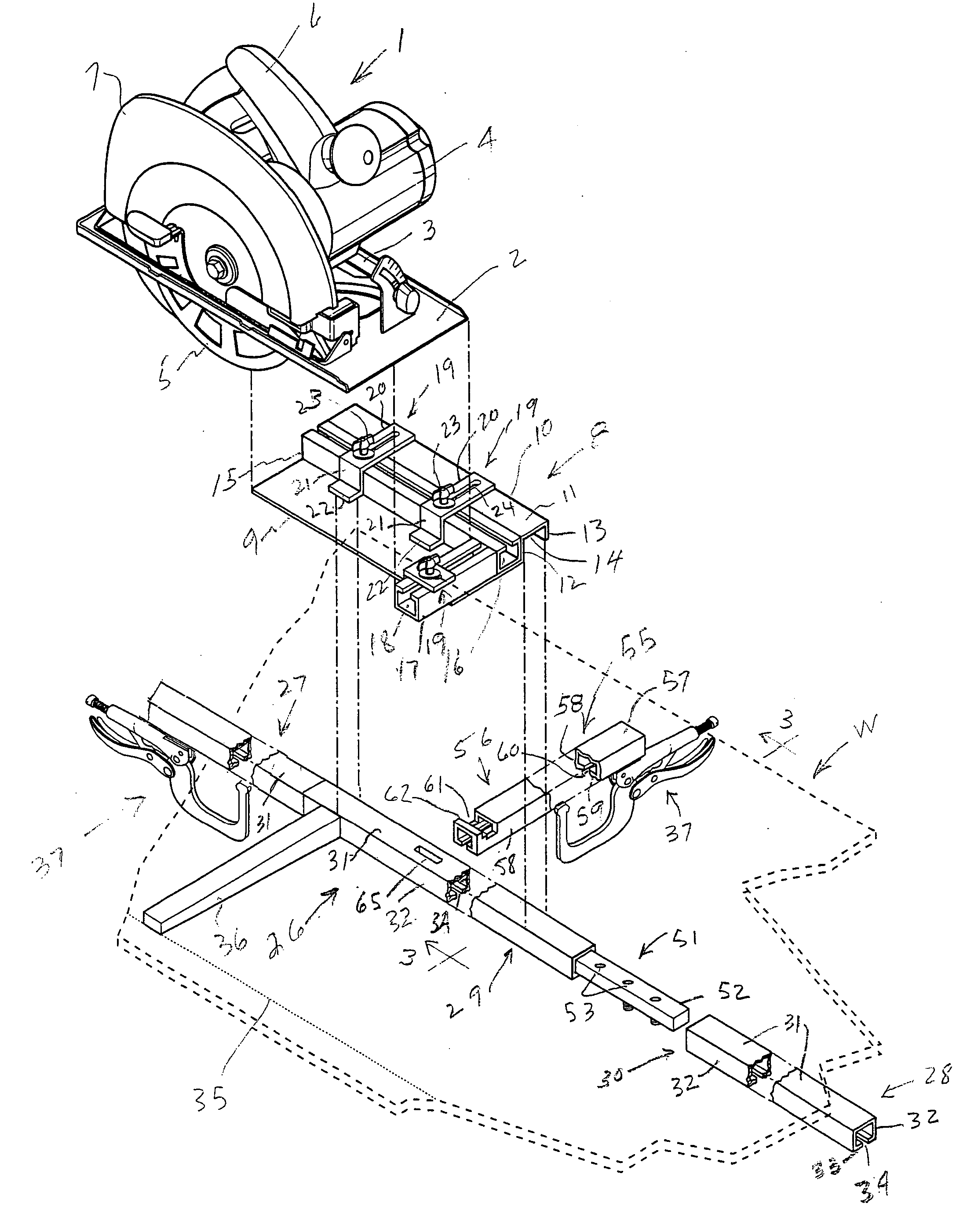
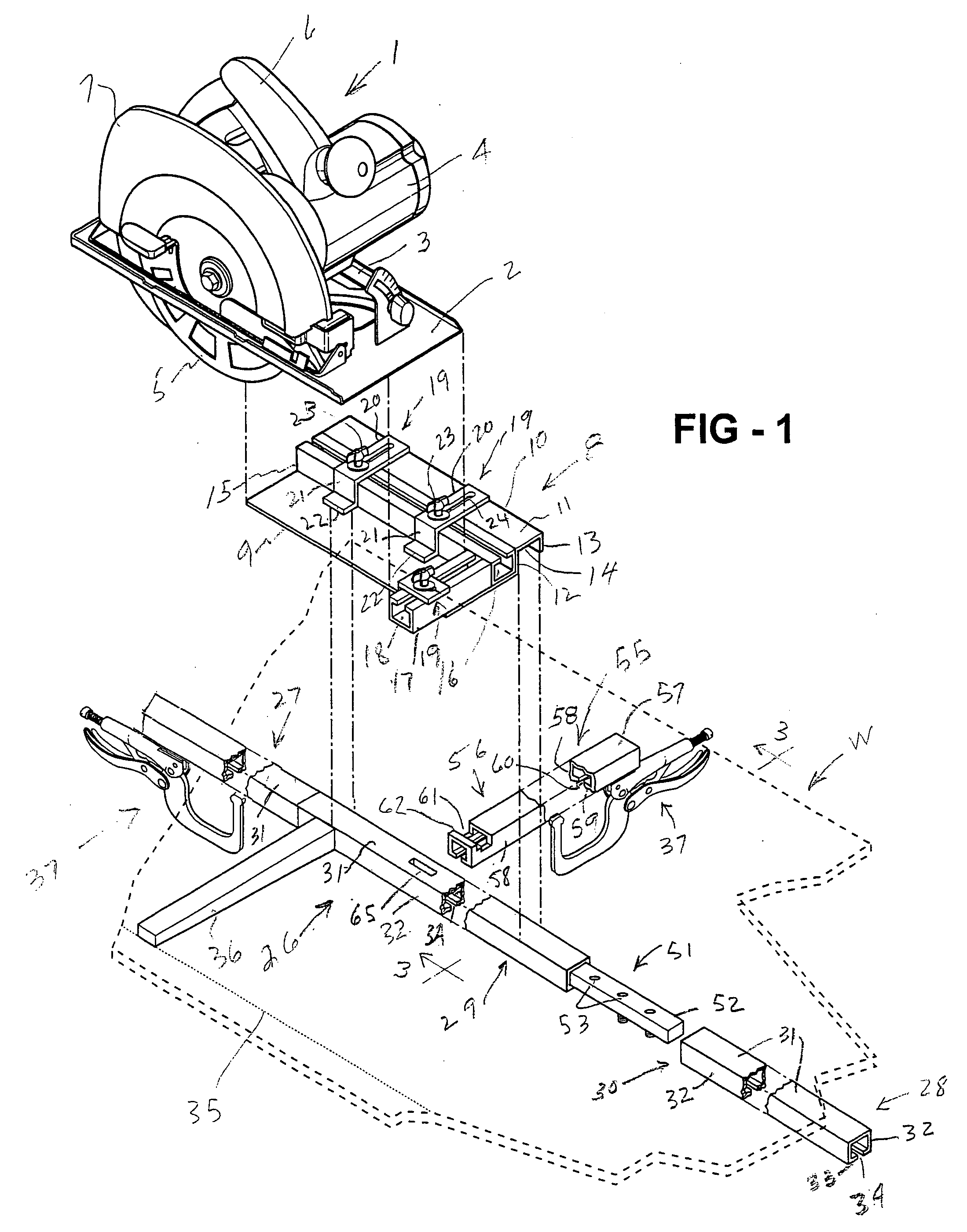
[0016] Apparatus constructed in accordance with the preferred embodiment of the invention is adapted for use in conjunction with a conventional circular saw 1 having a base 2 on which a supporting frame 3 is secured. The saw has a driving motor 4 which drives a rotary blade 5. The saw also has a handle 6 and a guard 7, all of which are conventional.

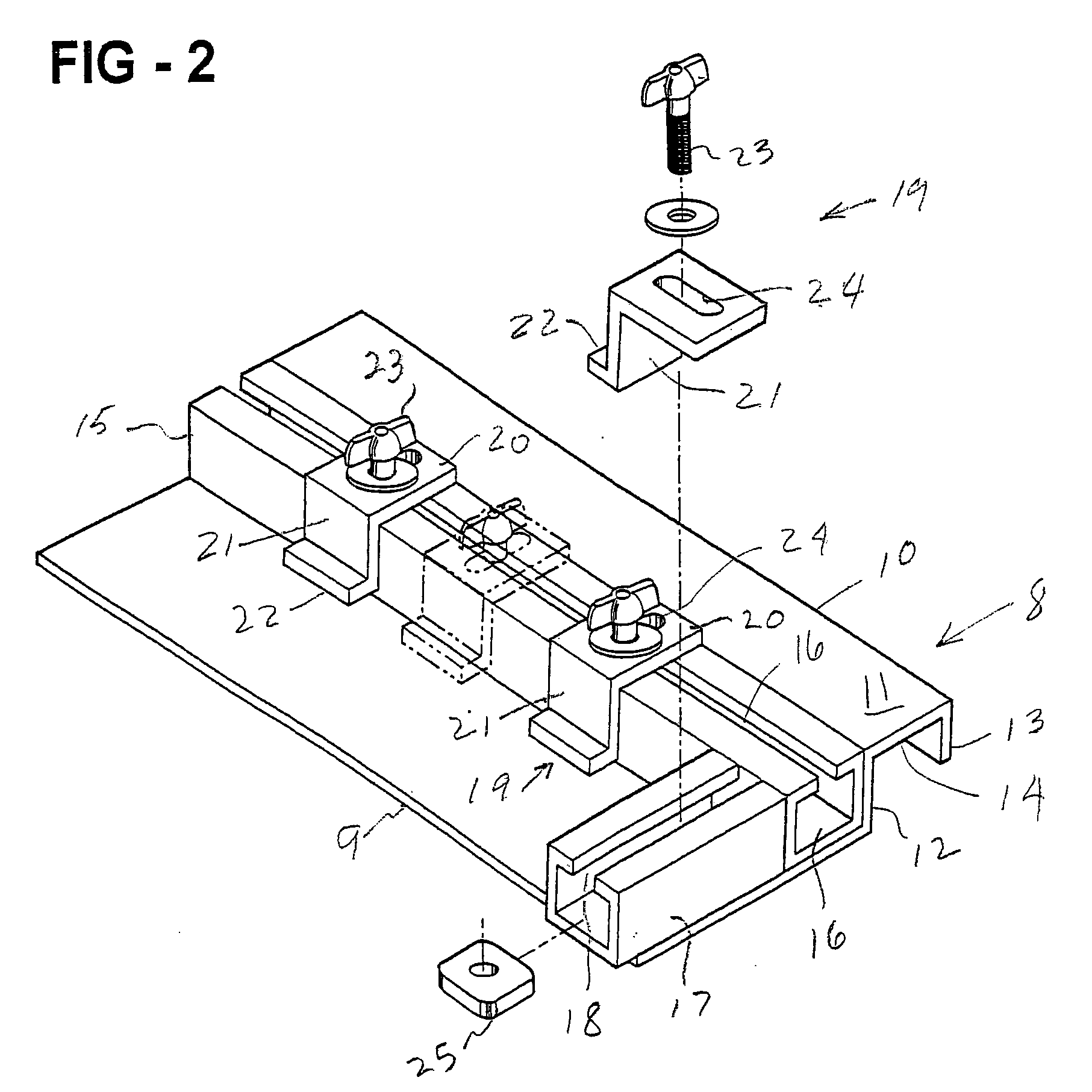
[0017] The circular saw is adapted to have its base 2 removably secured atop a carriage 8 comprising a slide plate 9 terminating at one edge in a guide slide 10 having a top 11 and spaced apart sides 12 and 13 which, together, form a channel 14. The side 12 abuts a mounting member 15 having a T-shaped slot 16 therein, the member 15 being secured to the plate 9. A similar mounting member 17 is secured to one end of the mounting plate 9 and has a similar T-slot 18 therein.

[0018] The base 2 of the saw 1 is adapted to be placed atop the slide plate 9 and secured thereto by clamps 19, each of which has a strap 20 which overlies the associate...


PUM

PropertyMeasurementUnit
lengthaaaaaaaaaa
widthaaaaaaaaaa
lengthaaaaaaaaaa

Abstract

Guide apparatus for guiding a tool such as a saw or router along a predetermined path relative to a workpiece has one or more track sections forming an elongate track parallel to the path to be followed by the tool. A tool-supporting carriage cooperates with the guide track so as to be guided by the track during movements of the tool. A stabilizer bar may be interlocked with the track in such manner as to prevent movement of the track laterally of the path along which the tool is to move.

Description

[0001] This invention relates to saw guide apparatus and more particularly to apparatus which is especially adapted for use in guiding a circular saw or other tool along a selected path relative to a workpiece. BACKGROUND OF THE INVENTION [0002] Circular saws are used conventionally for the cutting of relatively short workpieces, whereas table saws, rip saws, and panel saws are used for cutting larger workpieces. However, because the circular saw is compact, light weight, and easily transported and stored it is very much favored by carpenters at job sites. [0003] One of the difficulties of using a circular saw for cutting longer workpieces, such as dimension board up to eight or more feet in length, is the difficulty in guiding the saw accurately as it is moved along the workpiece. This difficulty is magnified in those instances in which the workpiece to be cut is ten feet in length. However, such longer workpieces are encountered quite frequently. [0004] An object of the invention ...

Claims


Application Information

Patent Timeline
Patent Type & Authority Applications(United States)
IPC IPC(8): B23Q9/00
CPCB23Q9/0042Y10T83/68Y10T83/8763
Inventor CAUGHLIN, PATRICK J.SCHIHL, RAYMONE J.ANSON, ZENITH W.
Owner CUTTING EDGE INVENTIONS
Why Eureka
Try Eureka