Tool and method for its manufacture

a technology of tools and manufacturing methods, applied in the direction of manufacturing tools, saw chains, shaping tools, etc., can solve the problems of waste of materials, time and money, and determinants of time consumption,

Inactive Publication Date: 2005-03-24
CAMITO AB
View PDF5 Cites 7 Cited by
  • Summary
  • Abstract
  • Description
  • Claims
  • Application Information

AI Technical Summary

Problems solved by technology

To manufacture a tool in the above-outlined manner is extremely time-consuming and such manufacture is, as a result, often determinative of the time consumption required in the new manufacture of different products.
When a tool has become obsolescent, for example bec

Method used


Image

  • Tool and method for its manufacture
  • Tool and method for its manufacture
  • Tool and method for its manufacture

Examples


Embodiment Construction

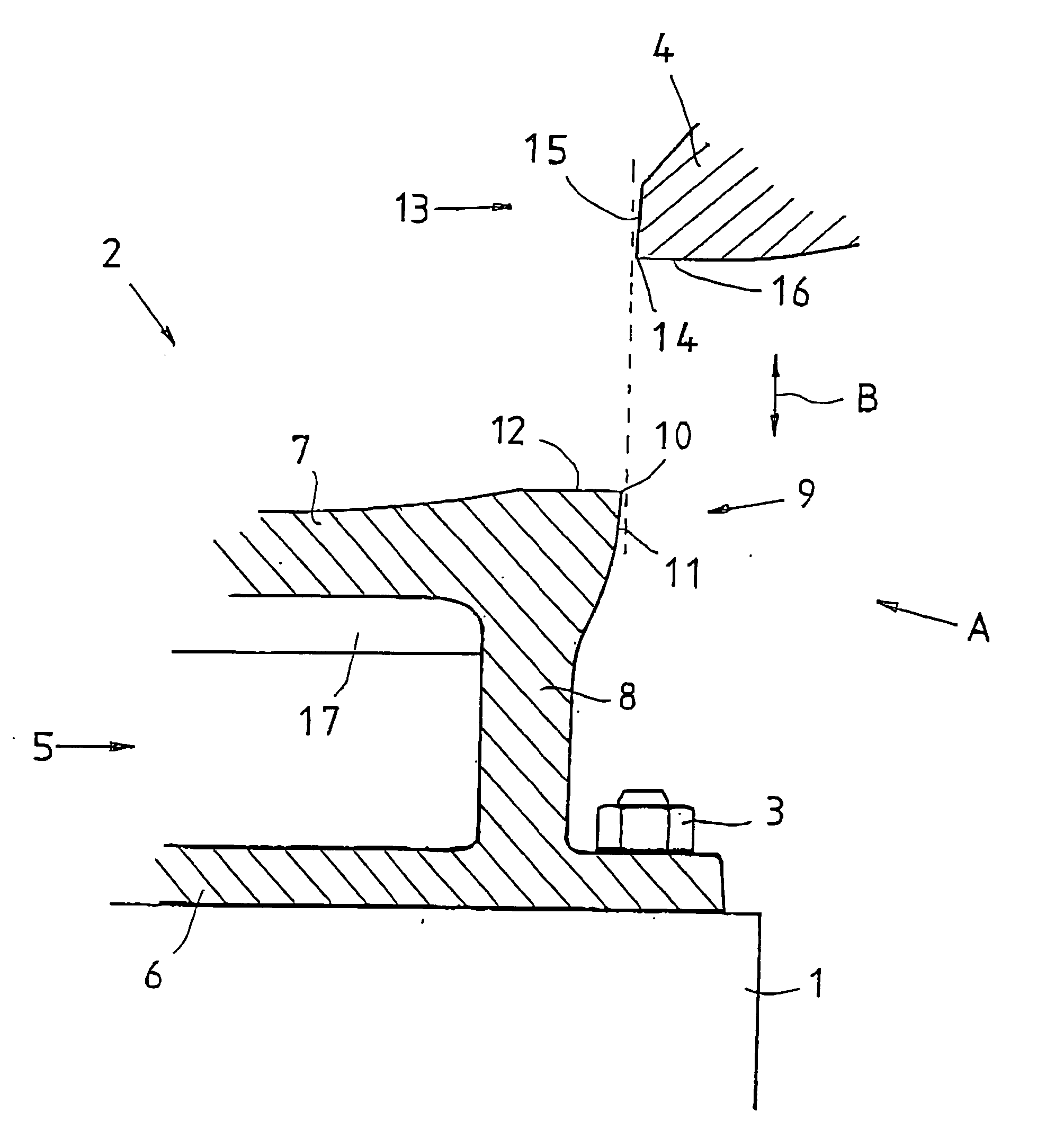
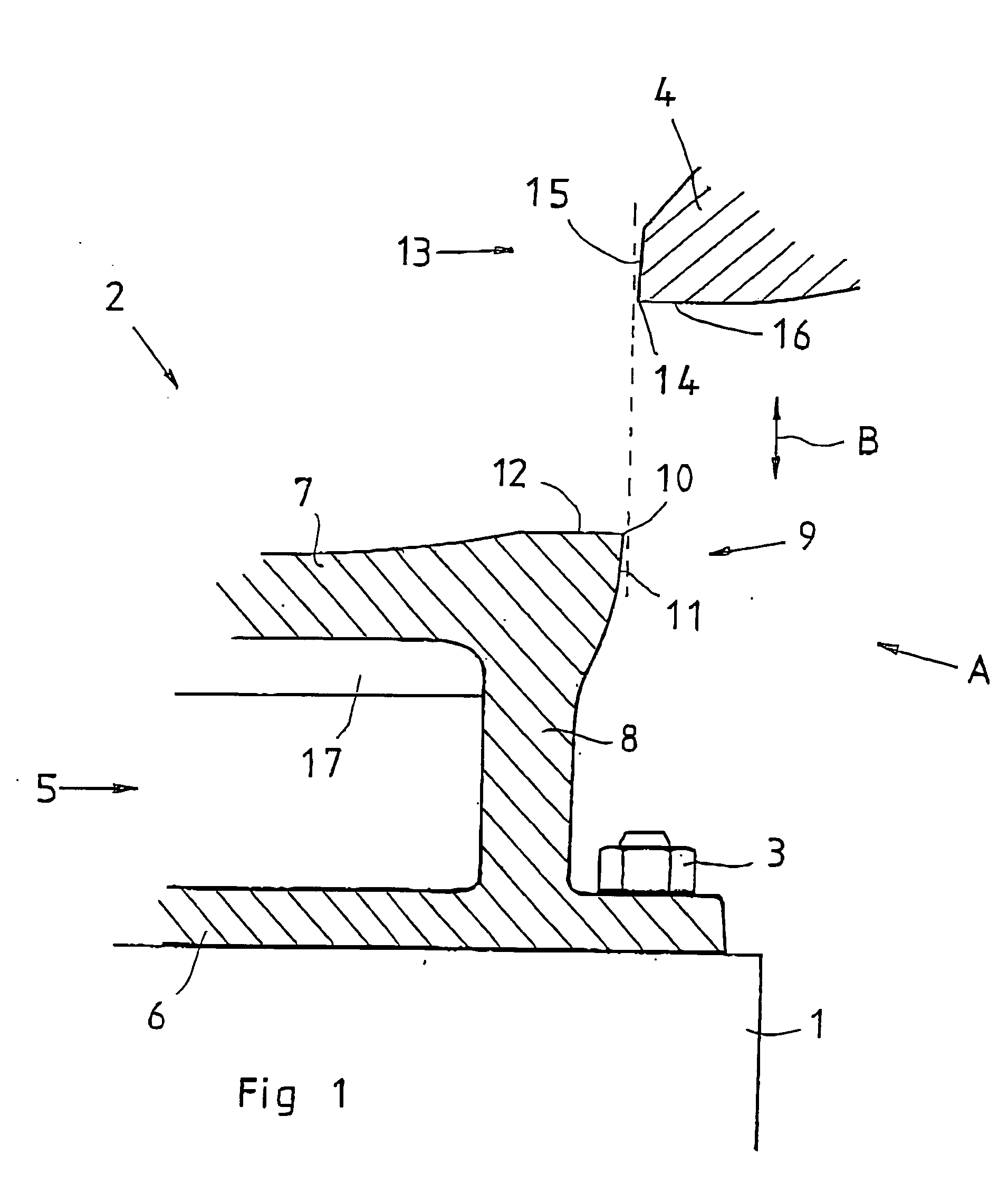
[0022] In FIG. 1, reference numeral 1 relates to a machine bed or foundation on which the tool 2 is secured by means of a bolt union 3.

[0023] The tool illustrated in FIG. 1 by way of example is a cutting tool which is in two parts and consists therefore of two tool parts, a lower tool part 2 and an upper tool part 4. The tool parts 2 and 4 are, however, in this context considered as separate tools.

[0024] A tool may be thought of as being composed of a plurality of different components, for example a tool body and a functional part in the illustrated example, the functional part would consist of a cutter which is intended to carrying out the processing operation together with a corresponding functional part on the upper tool 4.

[0025] In FIG. 1, the tool 2 includes a tool body 5 which has a lower mounting plate 6 for securing the tool on the tool table or bed 1. Further, the tool body 5 includes an upper part 7 which, in the illustrated embodiment, has rigidification ribs 17. The u...


PUM

PropertyMeasurementUnit
Compositionaaaaaaaaaa
Material propertiesaaaaaaaaaa

Abstract

A tool or a part thereof which has at least one tool body (7, 8) and one functional part (9) is cast in one united piece with at least two different casting materials (18, 20) of different material compositions, whereby the different parts of tool possess different material properties. Between the different tool parts, there is a clear interface in the material composition, but an intermingled transitional zone (19) of different material compositions is possible. In a method of manufacturing the tool, or a part thereof, casting material of at least two different material compositions is supplied to different parts (7, 8, 9, respectively) of the tool. The casting materials are kept separate and discrete from one another and, after the casting, there is thus obtained a tool possessing different material properties in different parts (7, 8; 9) of the tool.

Description

TECHNICAL FIELD [0001] The present invention relates to a tool or a part thereof for carrying out operations such as pressing, cutting, hemming and the like and includes at least a first and a second tool part with different functions in the tool, for example a tool body and an functional part disposed thereon in order, alone or together with some other additional functional part, or additional tool, to carry out the operation, the first and the second parts possessing different material properties. [0002] The present invention also relates to a method for manufacturing a tool or a part thereof, for carrying out operations such as pressing, cutting, hemming and the like, and entails that the tool is given different material properties in different parts of the tool. BACKGROUND ART [0003] In the manufacture of a tool for the above-outlined purpose, it has previously been the practice to separately manufacture a tool body which subsequently, in the example of a cutting tool, is provid...

Claims


Application Information

Patent Timeline
IPC IPC(8): B21D37/01B22D19/00B21D37/20B22D19/06B22D19/16
CPCB21D37/01B21D37/20B22D19/16B22D19/06B21D37/205Y10T83/9309
Inventor BERG, BENGTSVENSSON, CHRISTER
Owner CAMITO AB
Why Eureka
Try Eureka