Conveyor for continuous proofing and baking apparatus
a technology of conveyors and baking equipment, applied in the direction of mechanical equipment, transportation and packaging, driving chains, etc., can solve the problems of substantial cost savings, achieve substantial cost savings, facilitate the cleaning of conveyor tracks, and eliminate conveyor chain failures
- Summary
- Abstract
- Description
- Claims
- Application Information
AI Technical Summary
Benefits of technology
Problems solved by technology
Method used
Image
Examples
first embodiment
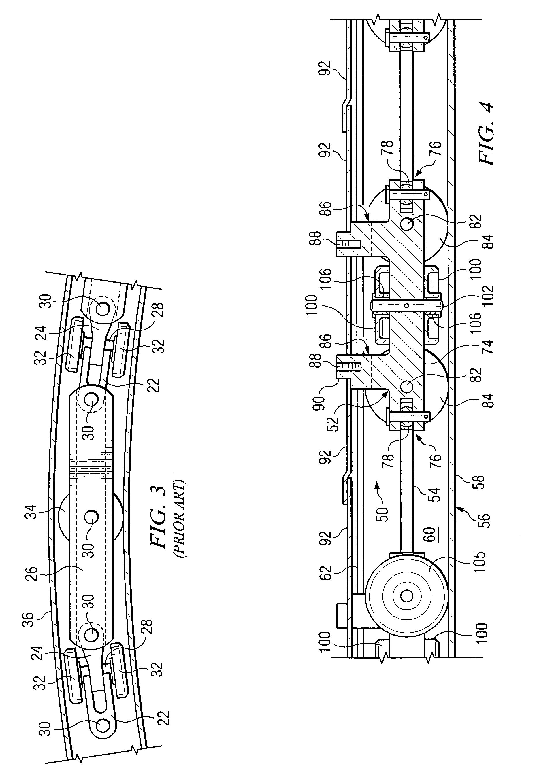
[0047] Referring now to the Drawings, and particularly to FIGS. 4, 5, 6, 7, 8, and 9 thereof, there is shown a conveyor chain 50 comprising the invention. The conveyor chain 50 comprises a plurality of identical compact carriages 52 which are connected end to end by a plurality of identical connection members 54. The conveyor chain 50 operates in a conveyor track 56 comprising a solid bottom wall 58; opposed, solid side walls 60; and a top wall 62 having a center slot 64 formed therein.
[0048] Each of the compact carriages 52 comprises a unitary structure which may be manufactured from a variety of materials utilizing conventional manufacturing techniques. For example, the compact carriages 52 may be manufactured from steel and / or other metals by means of die casting, investment casting, or other well known manufacturing processes. Alternatively, the compact carriages 52 may be formed from various plastic materials suitable for high temperature applications, and may be manufactured u...
second embodiment
[0094] Referring to FIG. 12, there is shown a conveyor chain 150 comprising the invention. The conveyor chain 150 comprises a plurality of identical compact carriages 152 which are connected end to end by a plurality of identical connection members 154. The conveyor chain 150 operates in a conveyor track 156 comprising a solid bottom wall 158; opposed, solid side walls 160; and a top wall 162 having a center slot formed therein.
[0095] Each of the compact carriages 152 comprises a unitary structure which may be manufactured from a variety of materials utilizing conventional manufacturing techniques. For example, the compact carriages 152 may be manufactured from steel and / or other metals by means of die casting, investment casting, or other well known manufacturing processes. Alternatively, the compact carriages 152 may be formed from various plastic materials adapted for high temperature applications, and may be manufactured utilizing conventional processes such as injection molding...
third embodiment
[0103] Referring to FIG. 13, there is shown a conveyor chain 250 comprising the invention. The conveyor chain 250 comprises a plurality of identical compact carriages 252 which are connected at equally spaced intervals along a wire rope 254. The conveyor chain 250 operates in a conveyor track 256 comprising a solid bottom wall 258; opposed, solid side walls 260; and a top wall 262 having a center slot formed therein.
[0104] Each of the compact carriages 252 comprises a unitary structure which may be manufactured from a variety of materials utilizing conventional manufacturing techniques. For example, the compact carriages 252 may be manufactured from steel and / or other metals by means of die casting, investment casting, or other well known manufacturing processes. Alternatively, the compact carriages 252 may be formed from various plastic materials suitable for high temperature applications, and may be manufactured utilizing conventional processes such as injection molding. Preferabl...
PUM
 Abstract
Description
Claims
Application Information
 - R&D
- Intellectual Property
- Life Sciences
- Materials
- Tech Scout
- Unparalleled Data Quality
- Higher Quality Content
- 60% Fewer Hallucinations
Browse by: Latest US Patents, China's latest patents, Technical Efficacy Thesaurus, Application Domain, Technology Topic, Popular Technical Reports.
© 2025 PatSnap. All rights reserved.Legal|Privacy policy|Modern Slavery Act Transparency Statement|Sitemap|About US| Contact US: help@patsnap.com


