Aircraft

a technology of aircraft and cranes, applied in the field of aircraft, can solve the problems of increasing the cost of cranes, increasing the cost of crane transport from one building site to another, etc., and achieve the effect of reducing the inherent weight of aircraft and contributing to the stability of flight attitud

Inactive Publication Date: 2005-03-24
WOBBEN ALOYS
View PDF20 Cites 48 Cited by
  • Summary
  • Abstract
  • Description
  • Claims
  • Application Information

AI Technical Summary

Benefits of technology

[0013] In a particularly preferred feature the aircraft according to the invention has a device for automatic control of the flight attitude and / or the flight altitude. That device can also be coupled to a GPS system in order in that way to provide for automatically heading for a predeterminable position. In that way rough positioning of the aircraft according to the invention can be effected automatically.
[0014] In order to reduce the inherent weight of the aircraft to the minimum possible extent, even when the flight control system is installed on the aircraft, the device is preferably arranged with connecting bars between at least two motors. In that case the device is particularly preferably arranged beneath the plane in which the bars extend between the motors. In that way, even in the case of a flight without a load, the aircraft has a low center of gravity which contributes to the stability of its flight attitude.

Problems solved by technology

That in turn results in larger and heavier cranes.
Those cranes are then in turn more and more expensive and the expenditure for transporting such a crane from one building site to another also rises, as also the expenditure for assembly and dismantling of the crane.
A disadvantage with that known aircraft however is that the electric motors are mounted to a common platform.
That platform on the one hand is of a high inherent weight and, due to the construction involved, predetermines the possible numbers of motors and rotors respectively.

Method used


Image

  • Aircraft
  • Aircraft
  • Aircraft

Examples


Embodiment Construction

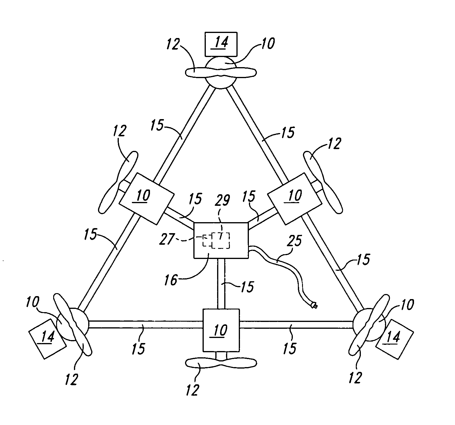
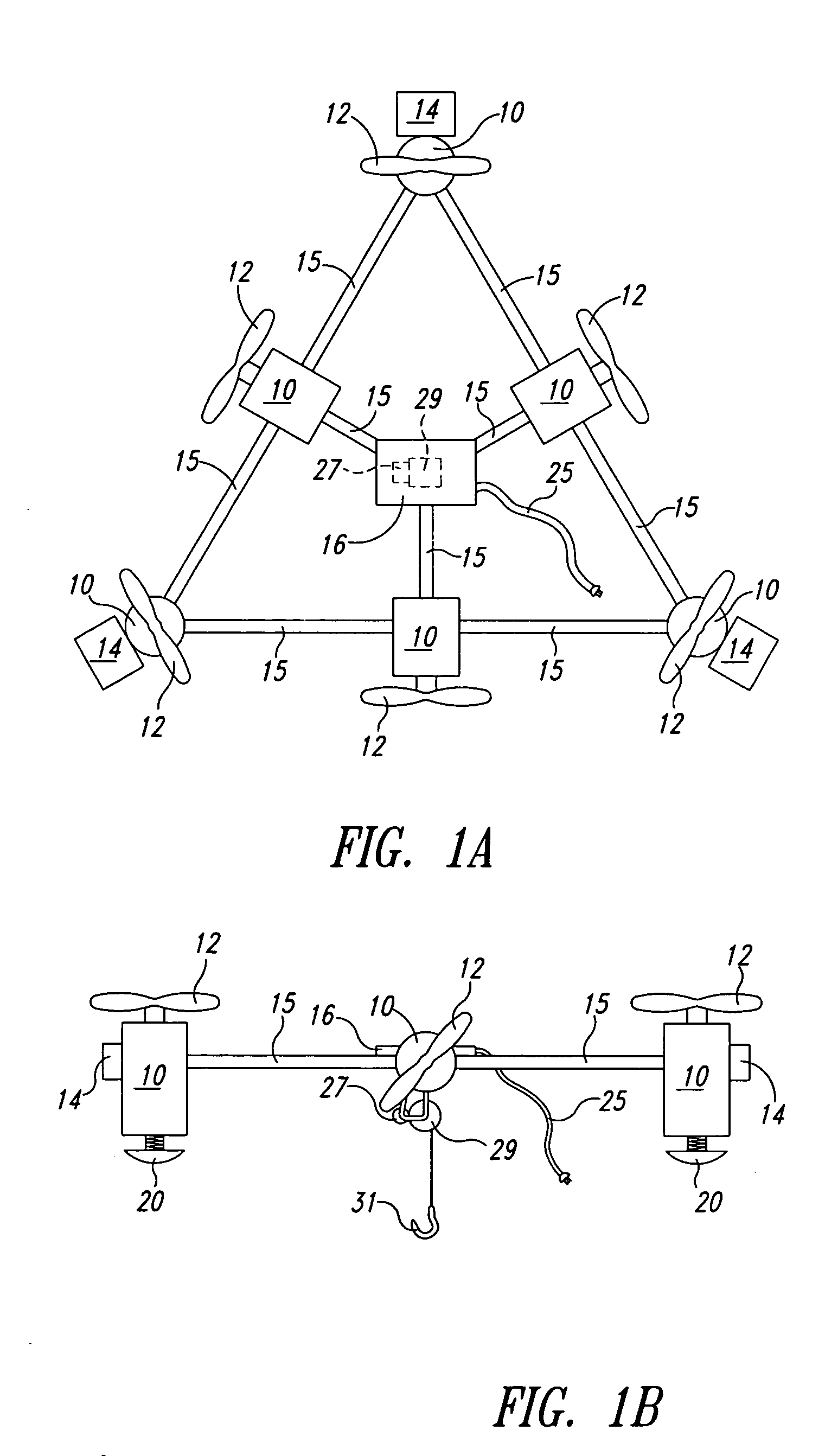
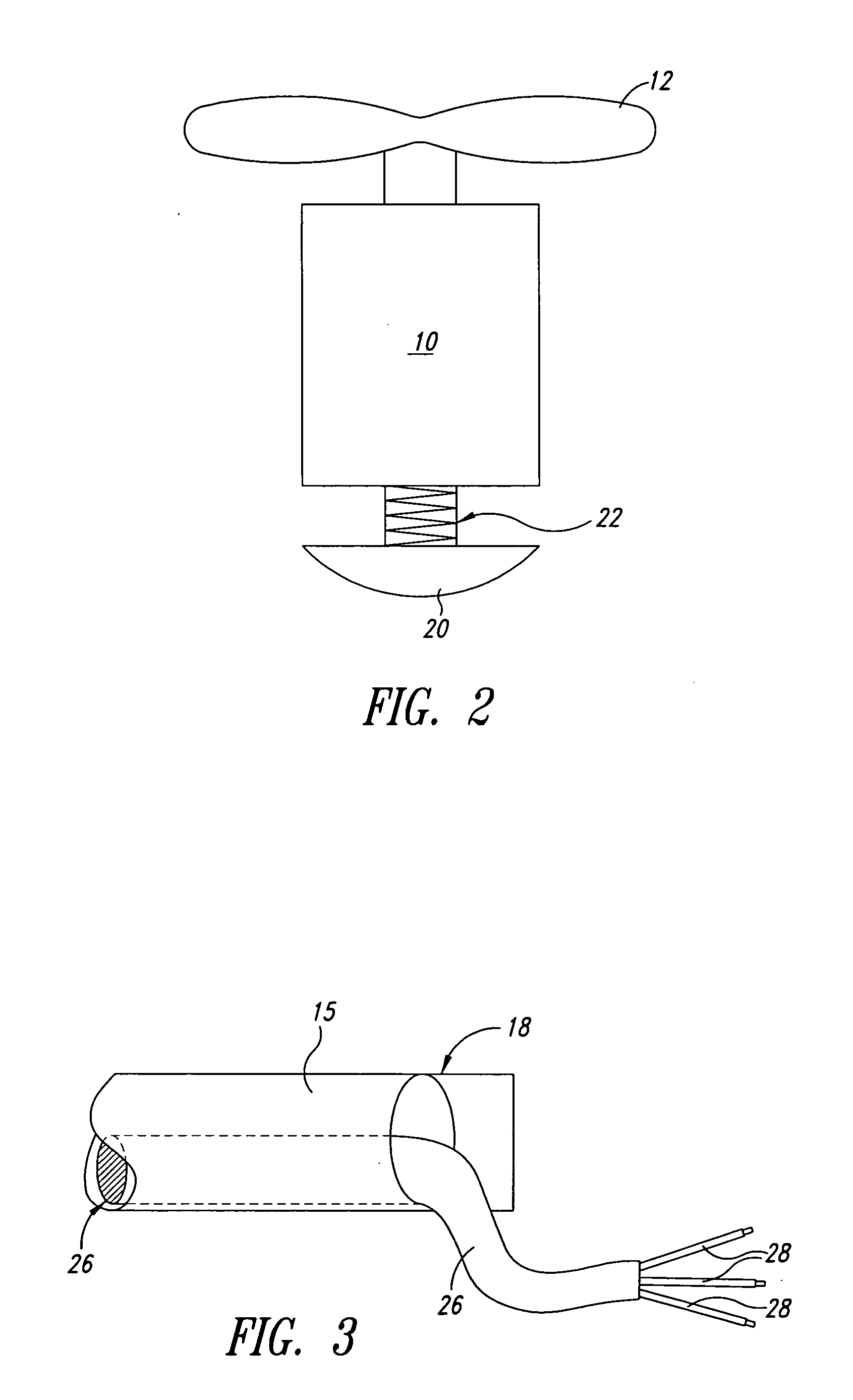
[0024] In FIGS. 1A and 1B, reference 10 denotes a motor, reference 12 denotes the rotor, such as a propeller, reference 14 denotes the inverter, reference 15 denotes a connecting bar and reference 16 denotes a control device for controlling the flight attitude or position, and / or the flight altitude.

[0025] The aircraft according to the invention is here shown as being of a triangular basic shape.

[0026] Some of the motors 10 are so arranged that the rotor 12 thereof rotates in a vertical plane. Depending on the direction of rotation of the motor 10 such a rotor 12 acts as a pusher rotor or a traction rotor. The direction of flight is accordingly influenced with those rotors.

[0027] A power supply cable 25 provides power from the ground to the control device, which provides and controls power to the motors 10 via respective cables 26.

[0028] Arranged at the end points of the triangular shape are further motors 10, the rotors 12 of which rotate in a substantially horizontal plane. Th...


PUM


Abstract

The present invention concerns an aircraft having a plurality of lifting and thrust rotors, with an electric motor and an inverter for each motor. In order to provide an aircraft having a greater payload, connecting bars are provided between the motors. In that respect the invention is based on the realization that, if such connecting bars are arranged in the manner of a latticework, they can provide a light but nonetheless stable structure for the aircraft, and that structure can carry correspondingly greater loads.

Description

BACKGROUND OF THE INVENTION [0001] 1. Field of the Invention [0002] This invention relates to an aircraft for lifting heavy loads, and more particularly, to a barge type aircraft with a plurality of electric lifting and thrusting motors that travels only a short distance above the ground. [0003] 2. Description of the Related Art [0004] A crane is usually required for erecting high buildings and constructions. That naturally also applies to tower-like buildings such as wind power installations. It will be noted that wind power installations are becoming increasingly larger and this means that the cranes on the one hand must reach ever increasing heights and on the other hand move ever increasing masses. That in turn results in larger and heavier cranes. Those cranes are then in turn more and more expensive and the expenditure for transporting such a crane from one building site to another also rises, as also the expenditure for assembly and dismantling of the crane. [0005] An alterna...

Claims


Application Information

Patent Timeline
Patent Type & Authority Applications(United States)
IPC IPC(8): B64C13/20B64C27/20B64C29/00B64C39/02B64D1/22B66F19/00
CPCB64C27/20B64C29/00B64C39/022B64C39/024B66F19/00B64C2201/042B64C2201/108B64C2201/165B64C2201/027B64U10/13B64U50/19B64U30/20B64U50/13B64C39/02F16L37/44
Inventor WOBBEN, ALOYS
Owner WOBBEN ALOYS
Why Eureka
Try Eureka