
Method for moving a headrest in the event of a rear-end collision and arrangement of a headrest on a vehicle seat

Inactive Publication Date: 2005-03-24
DAIMLER AG
View PDF11 Cites 11 Cited by
  • Summary
  • Abstract
  • Description
  • Claims
  • Application Information

AI Technical Summary

Benefits of technology

[0012] Starting from this prior art, the invention is based on the An object of the present invention is to provide a method for moving a head restraint in the event of a rear-end collision and an arrangement of a head restraint on a vehicle seat, with which the injuries in the region of the cervical spine in the event of a rear-end crash can be reduced even further without unnecessarily harming the occupant.
[0013] This object is achieved by a method first using at least one driving device to effect the movement and assisting the movement by vehicle occupant's upper body located on the vehicle seat and by an arrangement of a head restraint in a rear-end collision, the head restraint is movable in the forward direction of travel by the at least one drive device and an impact device which absorbs a rearward movement of the vehicle occupant's upper body located on the vehicle seat.
[0014] In the case of the method and the arrangement of a head restraint on a vehicle seat according to the invention, the combination of the movement of the head restraint in the event of a rear-end collision in the forward direction of travel by way of a drive device and this movement being assisted by a movement of an upper body of an occupant located on the vehicle seat being transmitted has proven very advantageous. A system operating in such a manner, in which preferably first of all the activation by w

Problems solved by technology

Investigations have revealed that, in particular in the event of rear-end collisions, serious injuries to the cervical spine occur in large numbers.
Such injuries to the cervical spine have proven problematic, in particular because the healing process is often very drawn out and is associated with high healing costs and corresponding demands made of insurance companies.
In the case of this system which is activated by the relative rearward movement of the occupant, it has proven disadvantageous that the triggering of the syste

Method used


Image

  • Method for moving a headrest in the event of a rear-end collision and arrangement of a headrest on a vehicle seat
  • Method for moving a headrest in the event of a rear-end collision and arrangement of a headrest on a vehicle seat
  • Method for moving a headrest in the event of a rear-end collision and arrangement of a headrest on a vehicle seat

Examples


Example

DETAILED DESCRIPTION OF THE DRAWINGS

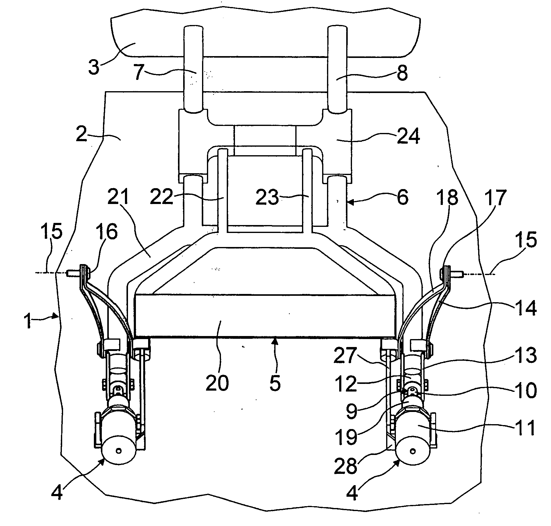
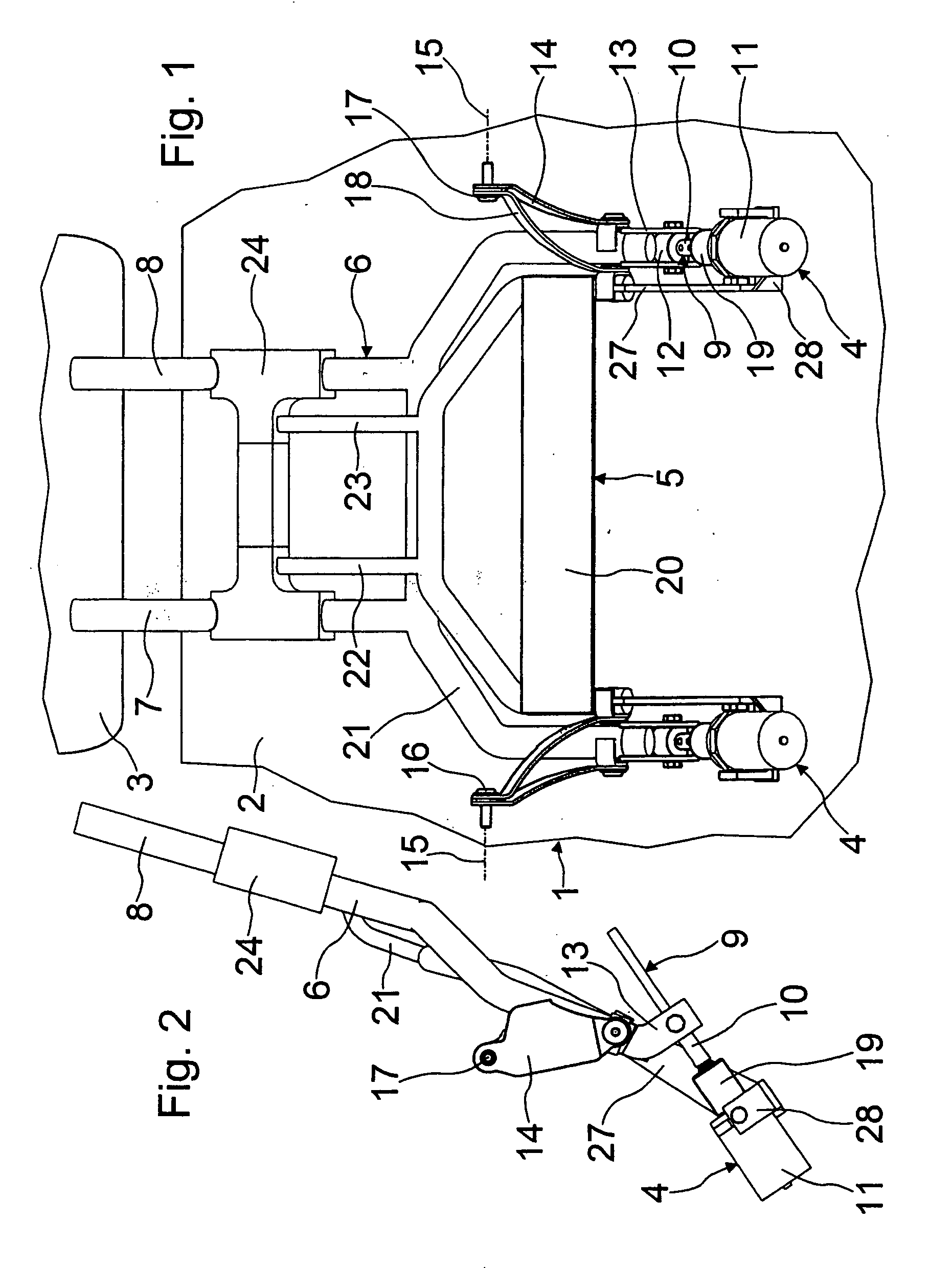
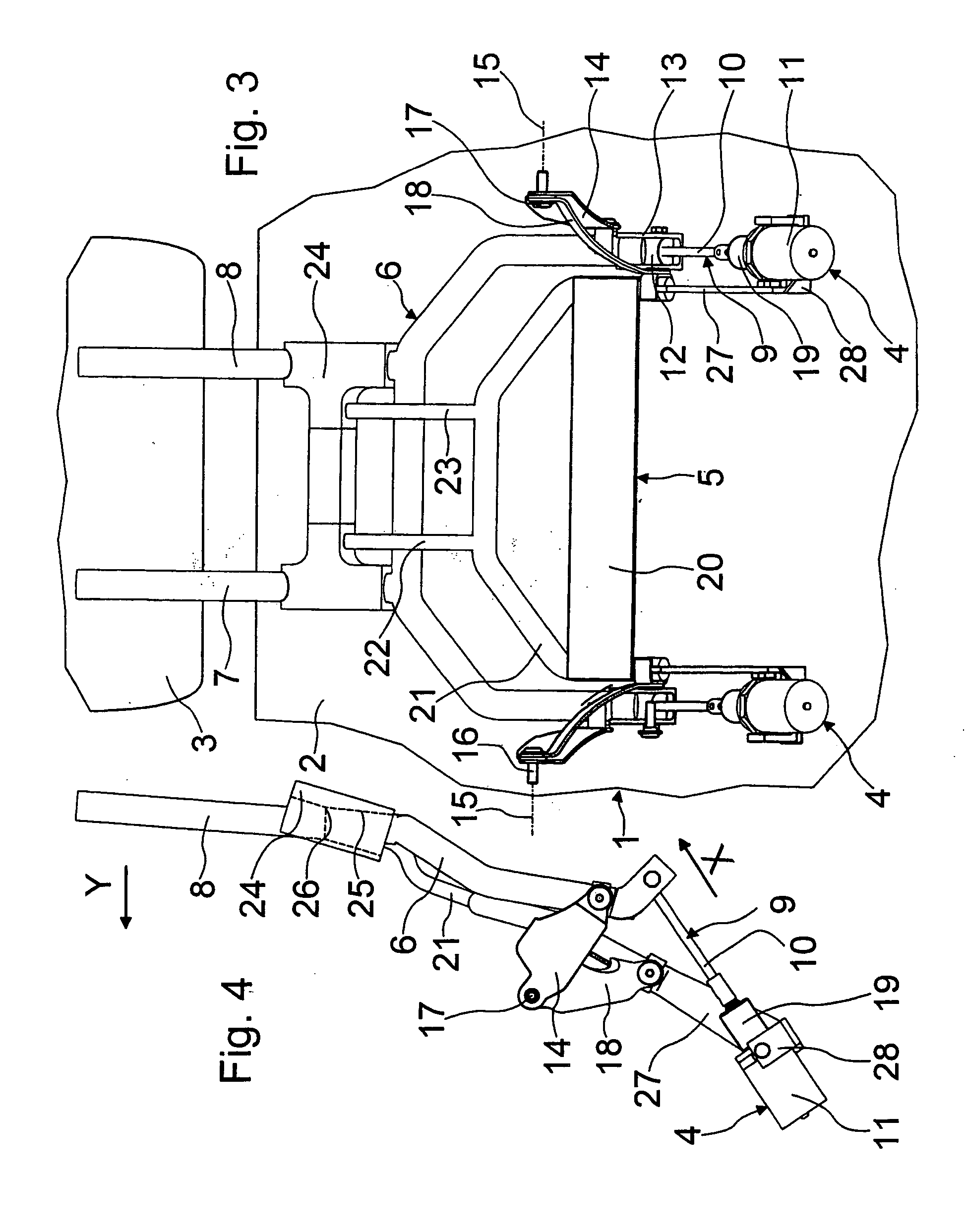
[0024] With reference now to the drawing figures, an upper region of a vehicle seat 1 of a motor vehicle is illustrated in part and in simplified form, with a backrest 2 (shown schematically) being connected to a head restraint 3.

[0025] The arrangement of the head restraint 3 on the vehicle seat 1 is provided such that, in the event of a rear-end collision, the head restraint 3 is moved in the forward direction of travel by way of a drive device 4 and an impact device 5 which absorbs the movement of an upper body of an occupant located on the vehicle seat 1.

[0026] A frame 6 which protrudes with two column-like tubes 7, 8 into the upholstery of the head restraint 3 is provided for holding the head restraint 3. The columns 7, 8 can be vertically adjustable in a conventional manner, thus enabling the height of the head restraint 3 to be matched to the height of the vehicle occupant's head.

[0027] In its region facing the backrest 2, the frame 6 fo...


PUM


Abstract

A method for moving a head restraint of a vehicle seat in the event of a rear-end collision and an arrangement of a head restraint on a vehicle seat are provided. In the event of a rear-end collision, the head restraint can be moved in the forward direction of travel by a drive device, and an impact device absorbs a rearward movement of an upper body of an occupant located on the vehicle seat.

Description

BACKGROUND OF THE INVENTION [0001] This application claims the priority of 101 42 926.6, filed Sep. 1, 2001, the disclosure of which is expressly incorporated by reference herein. [0002] The present invention relates to a method for moving a head restraint of a vehicle seat in the event of a rear-end collision, and to an arrangement of a head restraint on a vehicle seat, which arrangement is provided in particular for carrying out this method. [0003] Investigations have revealed that, in particular in the event of rear-end collisions, serious injuries to the cervical spine occur in large numbers. Such injuries to the cervical spine have proven problematic, in particular because the healing process is often very drawn out and is associated with high healing costs and corresponding demands made of insurance companies. [0004] It is, therefore, a great matter of concern for the vehicle industry to provide devices for protecting occupants in vehicles, in which the devices reduce or even ...

Claims


Application Information

Patent Timeline
IPC IPC(8): B60N2/48B60R21/055
CPCB60N2/4228B60N2/4885B60N2/4805B60N2/888B60N2/806
Inventor EBERLE, WALTERITINGER, ALBERT
Owner DAIMLER AG
Learn More