Tool for sensor management and fault visualization in machine condition monitoring

a technology of fault visualization and sensor management, applied in the field of monitoring power plant systems, can solve the problems of prior art failing to teach or suggest methods for efficient viewing and editing of sensor properties, and prior art failing to teach or suggest methods

Active Publication Date: 2005-03-24
SIEMENS ENERGY INC
View PDF8 Cites 17 Cited by
  • Summary
  • Abstract
  • Description
  • Claims
  • Application Information

AI Technical Summary

Benefits of technology

[0006] This present invention provides a method of monitoring sensors in a power plant system. In particular, the method provides an efficient tool for sensor management and fault visualization and navigation. The present invention permits an operator to obtain a comprehensive view of sensor properties and / or any sensor faults. The present invention may be able to display a fault status of each sensor in the plurality of sensors in a single display with the fault status for each sensor being displayed over time. The present invention may also provide a navigation mechanism that permits an operator to examine details of each sensor in the plurality of sensors. In addition, the present invention may be able to categorize each fault in the fault status using one or more properties or categorizing criteria.

Problems solved by technology

If the difference between actual sensor data and estimated value from the model exceeds a threshold for a sensor at a particular point in time, the monitoring system will indicate a fault for that sensor.
While there has been work on displaying the whole turbine machinery and showing faults at a particular window, the prior art does not teach or suggest methods that concentrated on the manner in which to display faults for a combination of sensors in time and in relation to each other on the same space.
The prior art fails to teach or suggest methods for efficient viewing and editing of properties of sensors relevant for monitoring / viewing purposes and reusing them in different statistical models.

Method used


Image

  • Tool for sensor management and fault visualization in machine condition monitoring
  • Tool for sensor management and fault visualization in machine condition monitoring
  • Tool for sensor management and fault visualization in machine condition monitoring

Examples


Embodiment Construction

[0014] The present invention is more particularly described in the following description and examples that are intended to be illustrative only since numerous modifications and variations therein will be apparent to those skilled in the art. As used in the specification and in the claims, the singular form “a,”“an,” and “the” may include plural referents unless the context clearly dictates otherwise. Also, as used in the specification and in the claims, the term “comprising” may include the embodiments “consisting of” and “consisting essentially of.”

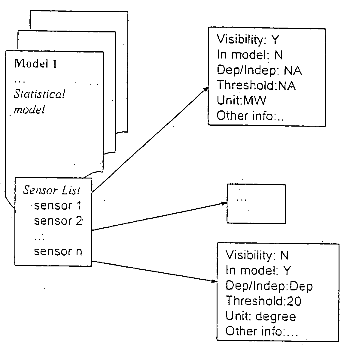
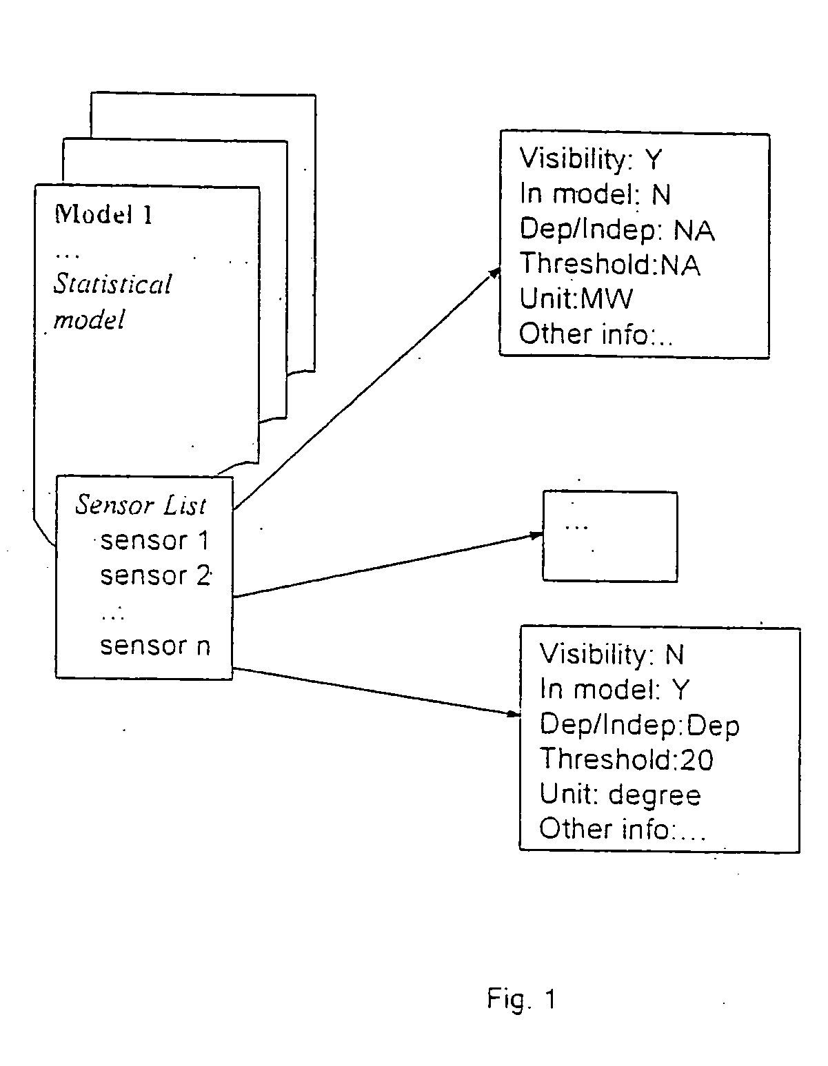
[0015] The present invention provides a method of managing sensors. The sensors may be used in a power plant monitoring system, or in any other system using a plurality of sensors for monitoring. The method utilizes two aspects: 1) a sensor management tool that permits the user to view and / or set the properties of sensors, such as the characteristics of the sensor (e.g. the unit in which the sensor is used, a description of the sensor), ...


PUM


Abstract

A tool for sensor management and fault visualization in machine condition monitoring. The method and system are able to monitor a plurality of sensors at one time. The sensors may be used in a power plant system monitoring system. The method and system may display a fault status for each sensor in the plurality of sensors in a single display, wherein the fault status for each sensor is displayed over time. The method and system also provide a mechanism that permits a user to examine details of each sensor in the plurality of sensors at any given time. In addition, the method and system are capable of categorizing each fault in the fault status using one or more properties or categorizing criteria. The method and system also permit sensors to be tested such that different operating models may be examined by utilizing different sensors.

Description

FIELD OF THE INVENTION [0001] This invention is directed generally to power plant systems, and more particularly to monitoring power plant systems. BACKGROUND [0002] In machine condition monitoring a model is trained based on sensor data collected during the normal operation of the plant. During monitoring sensor data is used as input to the trained model and it is checked if the test data are in agreement with the normal plant operation sensor data. If the difference between actual sensor data and estimated value from the model exceeds a threshold for a sensor at a particular point in time, the monitoring system will indicate a fault for that sensor. [0003] It is very important for the engineers to be able to view and edit the sensor properties, and especially the faults for the sensors in a fast and efficient way. [0004] While there has been work on displaying the whole turbine machinery and showing faults at a particular window, the prior art does not teach or suggest methods tha...

Claims


Application Information

Patent Timeline
Patent Type & Authority Applications(United States)
IPC IPC(8): G05B23/02
CPCG05B23/0272Y04S10/52
Inventor NEUBAUER, CLAUSCATALTEPE, ZEHRAYUAN, CHAOCHENG, JIEFANG, MINGMCCORKLE, WESLEY
Owner SIEMENS ENERGY INC
Why Eureka
Try Eureka