Electronic flash, electronic camera and light emitting head

Inactive Publication Date: 2005-03-24
FUJIFILM CORP
View PDF18 Cites 35 Cited by
  • Summary
  • Abstract
  • Description
  • Claims
  • Application Information

AI Technical Summary

Benefits of technology

[0014] Preferably, the electronic flash further comprises a color temperature determining device that determines a color temperature of subject light, wherein the light emission control device controls ratios between light emission amounts of the R, G and B light emitting diodes so that a color temperature of the light emitted from the electronic flash light source becomes the color temperature determined by the color temperature determining device. Thus, the color temperature of the electronic flash light can be automatically contro

Problems solved by technology

However, when an electronic flash is used to perform back light correction for the sun light in the morning or evening, the colors of the picture can be unnatural since the spectral characteristic

Method used


Image

  • Electronic flash, electronic camera and light emitting head
  • Electronic flash, electronic camera and light emitting head
  • Electronic flash, electronic camera and light emitting head

Examples


Example

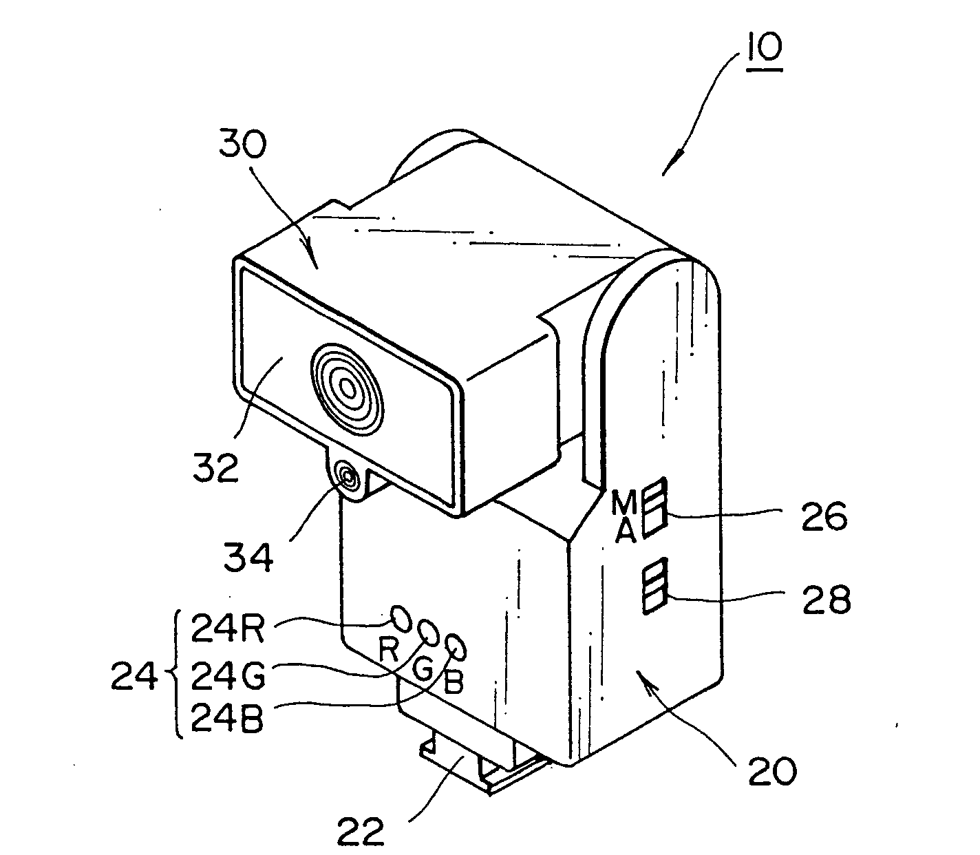
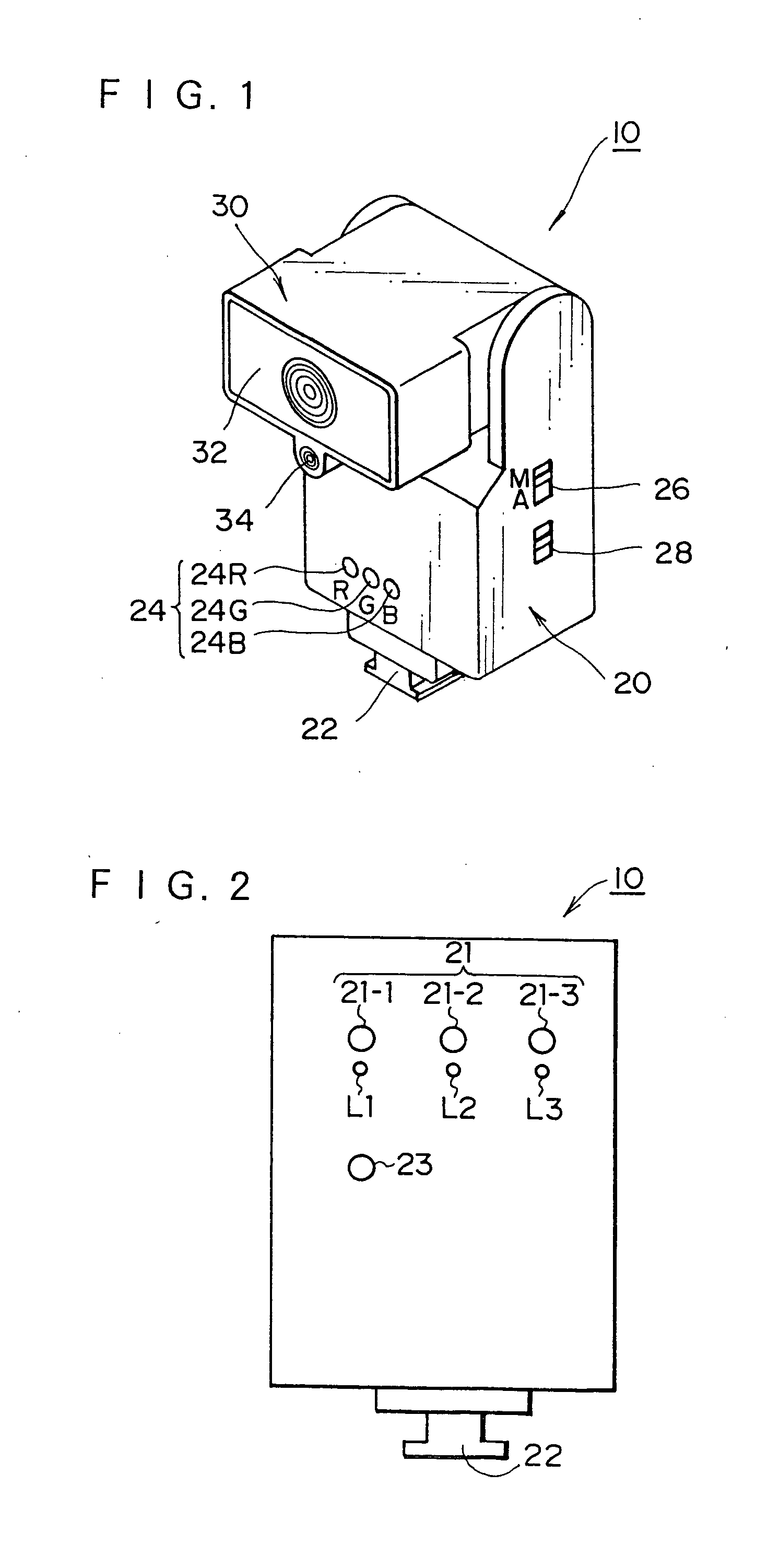
[0053]FIG. 1 is a perspective view of an electronic flash 10 for a camera of a first embodiment according to the present invention.

[0054] The electronic flash 10 is composed of a body 20 with a hot shoe 22 on its bottom and a light-emitting part 30.

[0055] Color temperature sensors 24 (photo sensors 24R, 24G and 24B with R, G and B filters) for measuring a color temperature of subject light are provided on the front of the body 20. A switch 26 for choosing a manual mode or an automatic mode and a color temperature setting switch 28 are provided on the side of the body 20. In the manual mode, a user manually sets a color temperature of an electronic flash light with a color temperature setting switch 28. In the automatic mode, the color temperature of the electronic flash light is automatically set.

[0056] A reference numeral 32 denotes a Fresnel lens of the light-emitting part 30, and a reference numeral 34 denotes a light-receiving sensor for adjusting the electronic flash light. ...

Example

[0091]FIG. 9 is a block diagram showing a second embodiment of an electronic flash 70 of the camera according to the present invention.

[0092] Unlike the electronic flash 10 of the first embodiment, the electronic flash 70 does not adjust the color temperature and has only a milky-white LED 71. Switches S1 and S2 turn on and off with an electronic flash switch. When the switches S1 and S2 are turned on, a step-up transformer 73 outputs a voltage from that of a battery 72 to charge a capacitor 74. When the switch S1 is turned on, an LED 75 for indicating the charging is turned on. When the voltage of the capacitor 74 reaches a reference voltage inputted to an operational amplifier 76, the charging is finished and the LED 75 turns off.

[0093] A switch S3 is a normally open switch, and it is closed for an instant when the shutter release button is pushed.

[0094] When the switch S3 is open, a capacitor 78 is charged to more than a predetermined voltage with a light-receiving sensor 77 f...

Example

[0098]FIG. 10 is a block diagram showing a third embodiment of an electronic flash 90 of the camera according to the present invention.

[0099] Unlike the electronic flash 10 of the first embodiment, the electronic flash 90 has an organic electroluminescence panel (organic EL panel) 91. Parts that are the same as those in FIG. 4 are denoted by the same reference numerals, and they will not be explained in detail.

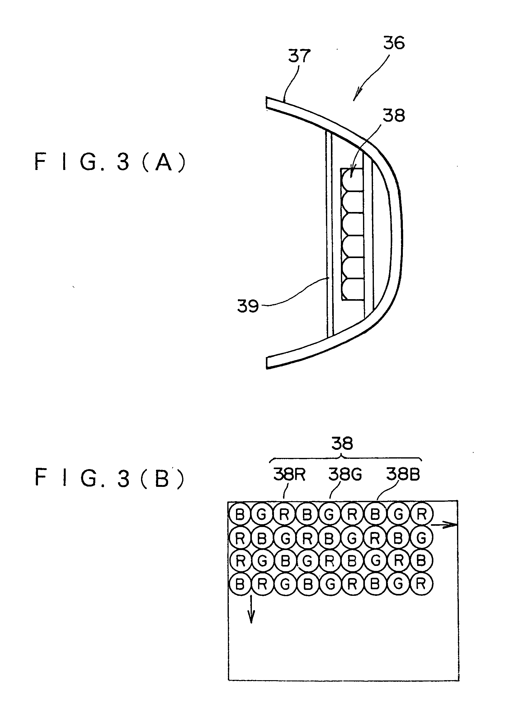
[0100] The organic EL panel 91 is formed in such a manner that R organic ELs whose spectrum peak wavelength is 600-740 nm (red area), G organic ELs whose spectrum peak wavelength is 500-600 nm (green area) and B organic ELs whose spectrum peak wavelength is 380-500 nm (blue area) are arranged in the same way as the LEDs 38 in FIG. 3(B). Light emitting brightnesses and times of the R, G and B organic ELs are controlled according to control signals inputted from the system controller 52.

[0101] This enables the organic EL panel 91 to emit a light with the desired color tempera...


PUM


Abstract

R, G and B LEDs are used as a light source of an electronic flash. Electric energy is supplied to a capacitor to the LEDs. A system controller controls light emitting amounts of the LEDs so that a color temperature of the electronic flash light becomes a color temperature that has been manually set with a color temperature setting switch or a color temperature of a light source determined by color temperature sensors.

Description

[0001] This application is a Divisional of co-pending application Ser. No. 09 / 911,736, filed on Jul. 21, 2001, and for which priority is claimed under 35 U.S.C. § 120; and this application claims priority of Application No. 2000-223505 filed in Japan on Jul. 25, 2000 and Application No. 2001-210598 filed in Japan on Jul. 11, 2001 under 35 U.S.C. § 119; the entire contents of all are hereby incorporated by reference.BACKGROUND OF THE INVENTION [0002] 1. Field of the Invention [0003] The present invention relates generally to an electronic flash, an electronic camera, and a light emitting head. The present invention relates more particularly to an electronic flash using light-emitting devices such as light emitting diodes (LEDs), an electronic camera and a light emitting head. [0004] 2. Description of the Related Art [0005] An electronic flash of a camera has a xenon tube as a light source. [0006] There have been high-luminance LEDs that emit red, green, amber, yellow, and milky-white...

Claims


Application Information

Patent Timeline
IPC IPC(8): G03B7/08H05B44/00G03B7/16G03B7/22G03B11/00G03B15/02G03B15/03G03B15/05H01L33/00H01L33/58H01L33/60H04N5/235
CPCG03B15/05H04N5/2354H04N9/735H05B33/0803H05B33/0818H04N9/04H05B33/0863H05B33/0869H05B33/0872Y02B20/346H05B33/0842G03B2215/0521G03B2215/0535G03B2215/0567H05B45/22H05B45/20H05B45/37Y02B20/30H05B45/325H04N23/673H04N23/631H04N23/74H04N23/88H04N23/10H04N23/667H04N25/75H04N25/713G03B2215/0592H04N5/77
Inventor KAWAKAMI, CHIKUNI
Owner FUJIFILM CORP
Why Eureka
Try Eureka