Joint-layer restoration in packet-over-optical networks

a technology of optical network and restoration capacity, applied in the field of optical network, can solve the problems of ineffective utilization of restoration capacity reserved in the transport layer, increased service protection cost, and inefficiency of bandwidth

Inactive Publication Date: 2005-03-24
LUCENT TECH INC
View PDF14 Cites 46 Cited by
  • Summary
  • Abstract
  • Description
  • Claims
  • Application Information

AI Technical Summary

Benefits of technology

Recently, advances in generalized multiprotocol label switching (GMPLS) and extensive study and understanding of packet-over-optical network architectures, have provided facilities that make it possible to manage the resources of the packet layer and underlying optical transport layer in an interoperable manner. We have recognized that these advances open up the possibility of coordinated restoration actions across the two layers.

Problems solved by technology

Bandwidth inefficiencies exist when restoration capacity that is reserved in the transport layer cannot be effectively utilized to minimize the cost of recovery from, for example, router failures in the packet layer.
Additionally, pure packet-layer restoration that cannot make use of restoration capacity set aside at the optical transport layer for transport-layer restoration, typically requires the reservation of expensive packet-layer service-ports, which increases the cost of service protection.

Method used


Image

  • Joint-layer restoration in packet-over-optical networks
  • Joint-layer restoration in packet-over-optical networks
  • Joint-layer restoration in packet-over-optical networks

Examples


Embodiment Construction

Reference herein to “one embodiment” or “an embodiment” means that a particular feature, structure, or characteristic described in connection with the embodiment can be included in at least one embodiment of the invention. The appearances of the phrase “in one embodiment” in various places in the specification are not necessarily all referring to the same embodiment, nor are separate or alternative embodiments mutually exclusive of other embodiments.

Introduction

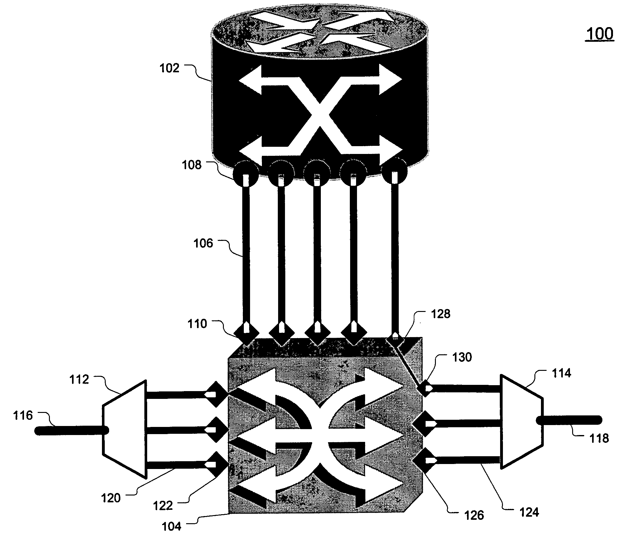
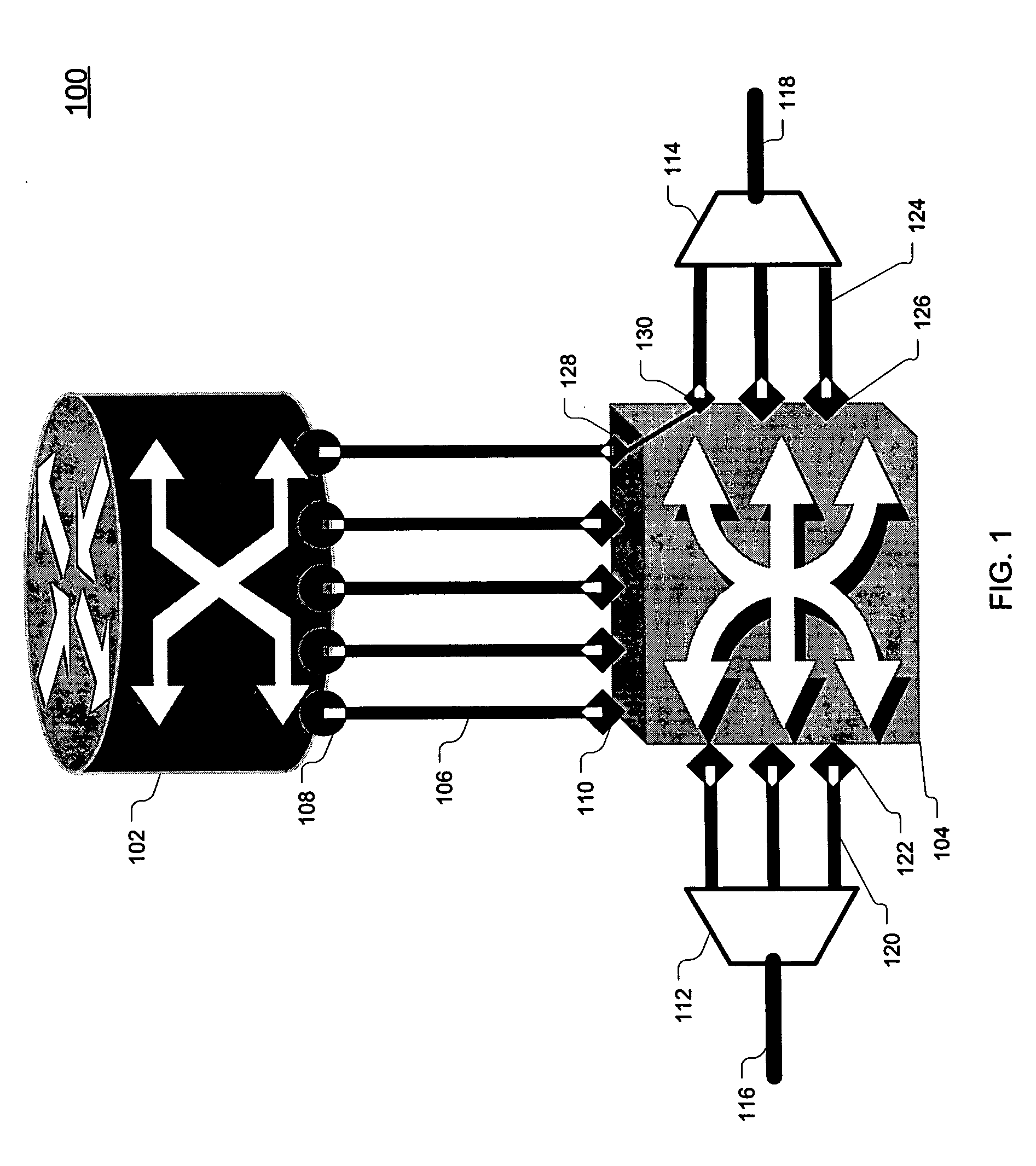
The present invention is applicable to a broad class of networks referred to generally as “packet-over-optical.” For specificity of discussion, in specific examples that follow, the packet layer is assumed to be IP / MPLS. However, as would be understood to one skilled in the art, the invention described herein is applicable to other packet technologies as well, including asynchronous transfer mode (ATM) and Frame Relay.

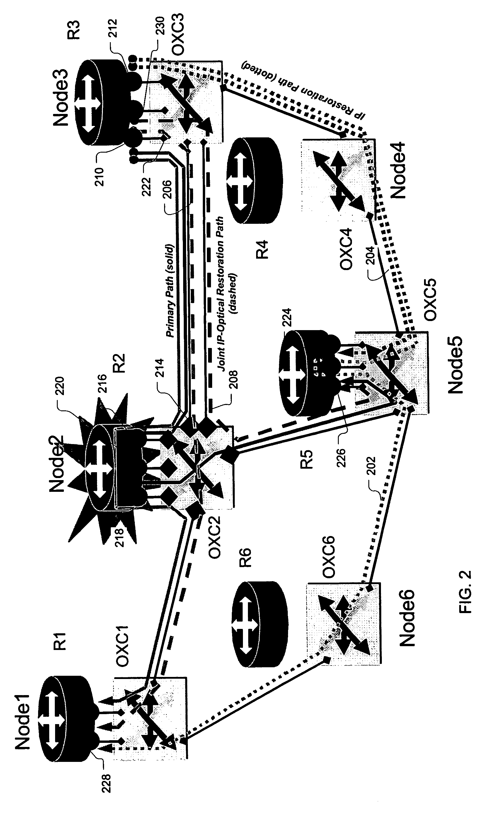
Typically, in today's telecommunication networks, the optical transport layer is used to recover from ...


PUM


Abstract

A joint “packet-optical” layer restoration mechanism protects against single, packet-layer router failures by managing network resources from both the packet layer and the optical transport layer in a synergistic manner. It reuses packet-layer router service-ports and / or transport-layer service wavelengths associated with optical switch-ports instead of reserving additional standby packet-layer router service-ports. It can reuse resources from primary paths that are unaffected by router failures and paths that exist for link-failure protection at the optical layer. Embodiments feature a modified node structure that includes both an IP router and a dynamically reconfigurable OXC, which dynamically establishes connectivity between IP-router ports and transport-layer optical fibers. The joint-layer router provides fine-granularity grooming at the IP layer and full-fledged wavelength networking via dynamic wavelength switching and / or wavelength translation at the optical layer. The latter can change the wavelength cross-connections on-demand to perform restoration or to modify the connectivity between IP routers in the network.

Description

BACKGROUND OF THE INVENTION 1. Field of the Invention The present invention relates to optical networks and, more specifically, to restoration planning in packet-over-optical networks. 2. Description of the Related Art A popular architecture for telecommunications networks is known as packet-over-optical. This architecture employs an optical transport layer, for example, a Synchronous Optical Network (SONET)) or frame relay layer, overlaid with a packet layer, for example, Internet protocol (IP), IP over multiprotocol label switched (MPLS), asynchronous transfer mode (ATM) or frame relay. With the deployment of high-capacity, for example, gigabit-per-second range, transmission and switching equipment within these networks, any single-link outage or single-node outage can lead to tremendous losses for both the network operators and their customers. As a result, it has become important to design these networks in such a way that they can quickly recover from network failure and re...

Claims


Application Information

Patent Timeline
Patent Type & Authority Applications(United States)
IPC IPC(8): H04J14/02H04L12/24H04L29/06H04Q11/00
CPCH04J14/0227H04J14/0284H04L41/0668H04J14/0241H04Q2011/0081H04L69/16H04L69/168H04Q11/0071
Inventor ATKINSON, GARY W.CHIGAN, CHUNXIAONAGARAJAN, RAMESH
Owner LUCENT TECH INC
Why Eureka
Try Eureka