Embedment device for fiber-enhanced slurry

a technology of enhanced slurry and embedding device, which is applied in the direction of butter manufacturing, turning machine accessories, drawing profiling tools, etc., can solve the problems of low panel strength, fibers applied in mats or webs, and insufficient structural strength, so as to reduce board line downtime

Active Publication Date: 2005-03-24
UNITED STATES GYPSUM CO
View PDF12 Cites 87 Cited by
  • Summary
  • Abstract
  • Description
  • Claims
  • Application Information

AI Technical Summary

Benefits of technology

[0012] Thus, there is a need for a device for thoroughly mixing fiberglass or other structural reinforcing fibers into a settable slurry in a way so that the device does not become clogged or impaired by chunks or setting slurry.
[0013] The above-listed needs are met or exceeded by the present invention that features an embedment device including at least a pair of elongate shafts disposed on the fiber-enhanced settable slurry board production line to traverse the line. The shafts are preferably disposed in spaced parallel relation to each other. Each shaft has a plurality of axially spaced disks along the shaft. During board production, the shafts and the disks rotate axially. The respective disks of the adjacent, preferably parallel shafts are intermeshed with each other for creating a “kneading” or “massaging” action in the slurry, which embeds previously deposited fibers into the slurry. In addition, the close, intermeshed and rotating relationship of the disks prevents the buildup of slurry on the disks, and in effect creates a “self-cleaning” action which significantly reduces board line downtime due to premature setting of clumps of slurry.

Problems solved by technology

However, a drawback of such conventional panels is that they do not have sufficient structural strength to the extent that such panels may be comparable to, if not stronger than, structural plywood or oriented strand board (OSB).
One drawback of conventional processes for producing cementitious panels is that the fibers, applied in a mat or web, are not properly and uniformly distributed in the slurry, and as such, the reinforcing properties resulting due to the fiber-matrix interaction vary through the thickness of the board, depending on the thickness of each board layer.
When insufficient penetration of the slurry through the fiber network occurs, poor bonding between the fibers and the matrix results, causing low panel strength.
Also, in some cases when distinct layering of slurry and fibers occurs, improper bonding and inefficient distribution of fibers causes poor panel strength development.
Another drawback of conventional processes for producing cementitious panels is that the resulting product is too costly and as such is not competitive with outdoor / structural plywood or oriented strand board (OSB).
One source of the relatively high cost of conventional cementitious panels is due to production line downtime caused by premature setting of the slurry, especially in particles or clumps which impair the appearance of the resulting board, and interfere with the efficiency of production equipment.
Significant buildups of prematurely set slurry on production equipment require shutdowns of the production line, thus increasing the ultimate board cost.
This is a particular problem when quick-setting slurries are created, as when fast setting agents or accelerators are introduced into the slurry.
A potential problem when creating cement structural panels in a moving production line, is for portions of the slurry to prematurely set, forming blocks or chunks of various sizes.
When these chunks break free and become incorporated into the final board product, they interfere with the uniform appearance of the board, and also cause structural weaknesses.

Method used


Image

  • Embedment device for fiber-enhanced slurry
  • Embedment device for fiber-enhanced slurry
  • Embedment device for fiber-enhanced slurry

Examples


Embodiment Construction

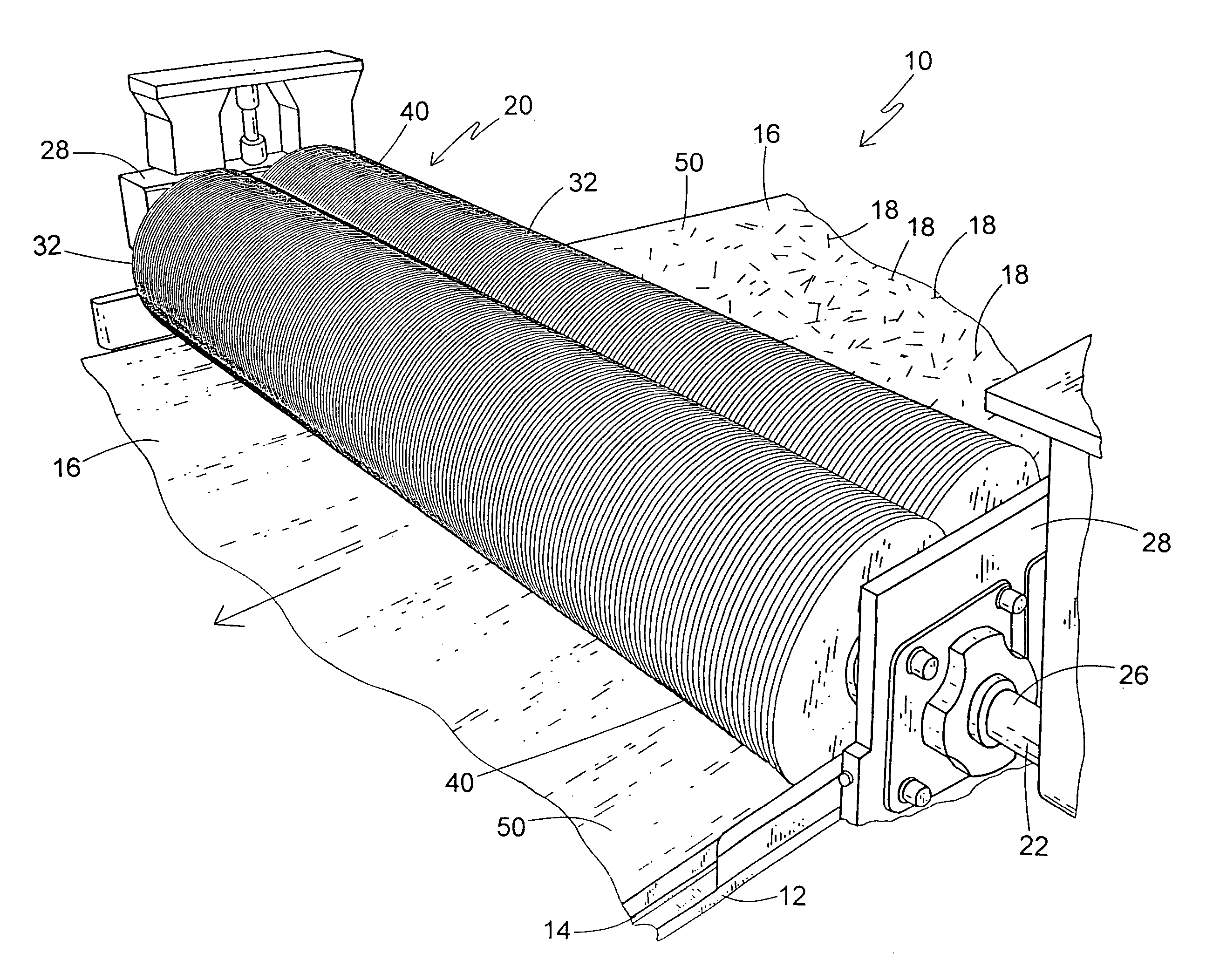
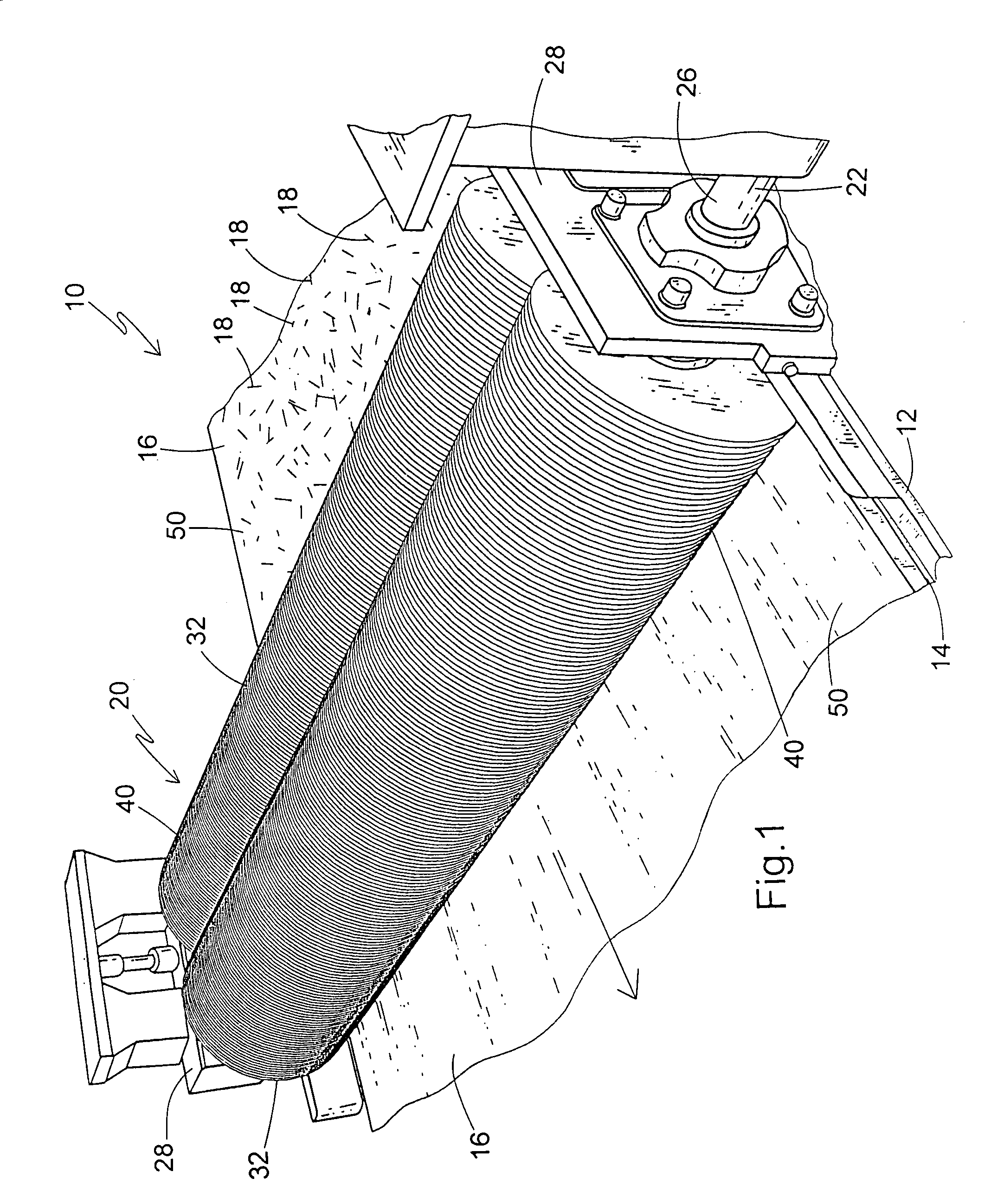
[0020] Referring now to FIGS. 1 and 2, a structural panel production line is fragmentarily shown and is generally designated 10. The production line 10 includes a support frame or forming table 12 which supports a moving carrier 14, such as a rubber-like conveyor belt, a web of craft paper, release paper, and / or other webs of support material designed for supporting a slurry prior to setting, as is well known in the art. The carrier 14 is moved along the support frame 12 by a combination of motors, pulleys, belts or chains and rollers (none shown) which are also well known in the art. Also, while the present invention is intended for use in producing structural cement panels, it is contemplated that it may find application in any situation in which bulk fibers are to be mixed into a settable slurry for board or panel production.

[0021] While other sequences are contemplated depending on the application, in the present invention, a layer of slurry 16 is deposited upon the moving carr...


PUM

PropertyMeasurementUnit
movementaaaaaaaaaa
diameteraaaaaaaaaa
thicknessaaaaaaaaaa

Abstract

An embedment device for use in a structural panel production line wherein a slurry is transported on a moving carrier relative to a support frame, and chopped fibers are deposited upon the slurry, includes a first elongate shaft secured to the support frame and having a first plurality of axially spaced disks, a second elongate shaft secured to the support frame and having a second plurality of axially spaced disks, the first shaft being disposed relative to the second shaft so that the disks intermesh with each other. The intermeshing relationship enhances embedment of the fibers into the slurry and also prevents clogging of the device by prematurely set slurry particles.

Description

CROSS REFERENCE TO RELATED APPLICATIONS [0001] This application is related to co-pending applications U.S. Ser. No. ______ entitled SLURRY FEED APPARATUS FOR FIBER-REINFORCED STRUCTURAL CEMENTITIOUS PANEL PRODUCTION (2033.66885) and U.S. Ser. No. ______ entitled MULTI-LAYER PROCESS AND APPARATUS FOR PRODUCING HIGH STRENGTH FIBER-REINFORCED STRUCTURAL CEMENTITIOUS PANELS (Attorney Docket No. 2033.66886), filed concurrently herewith and herein incorporated by reference.FIELD OF THE INVENTION [0002] This invention relates generally to devices for embedding fibers in settable slurries, and specifically to a device designed for embedding fibers in a settable cement slurry along a cement board or cementitious structural panel (“SCP”) production line. [0003] Cementitious panels have been used in the construction industry to form the interior and exterior walls of residential and / or commercial structures. The advantages of such panels include resistance to moisture compared to standard gyps...

Claims


Application Information

Patent Timeline
Patent Type & Authority Applications(United States)
IPC IPC(8): B01F7/00B01F13/00B01F15/00B28C5/14B28C5/36B28C5/40
CPCB01F7/0045B01F13/0013B28C5/40B28C5/365B28C5/147B01F27/115B01F33/26
Inventor PORTER, MICHAEL J.
Owner UNITED STATES GYPSUM CO
Why Eureka
Try Eureka