Methods of operation for controlled temperature combustion engines using gasoline-like fuel, particularly multicylinder homogenous charge compression ignition (HCCI) engines

Inactive Publication Date: 2005-03-24
ENVIRONMENTAL PROTECTION AGENCY US
View PDF6 Cites 19 Cited by
  • Summary
  • Abstract
  • Description
  • Claims
  • Application Information

AI Technical Summary

Benefits of technology

[0004] The present invention provides an HCCI engine with a control system to maintain stable, efficient, low emission HCCI combustion during engine transitions from one sp

Problems solved by technology

However, absent from the prior art is a practical method for controlling the initiation of combustion in an HCCI engine to t

Method used


Image

  • Methods of operation for controlled temperature combustion engines using gasoline-like fuel, particularly multicylinder homogenous charge compression ignition (HCCI) engines
  • Methods of operation for controlled temperature combustion engines using gasoline-like fuel, particularly multicylinder homogenous charge compression ignition (HCCI) engines
  • Methods of operation for controlled temperature combustion engines using gasoline-like fuel, particularly multicylinder homogenous charge compression ignition (HCCI) engines

Examples


Embodiment Construction

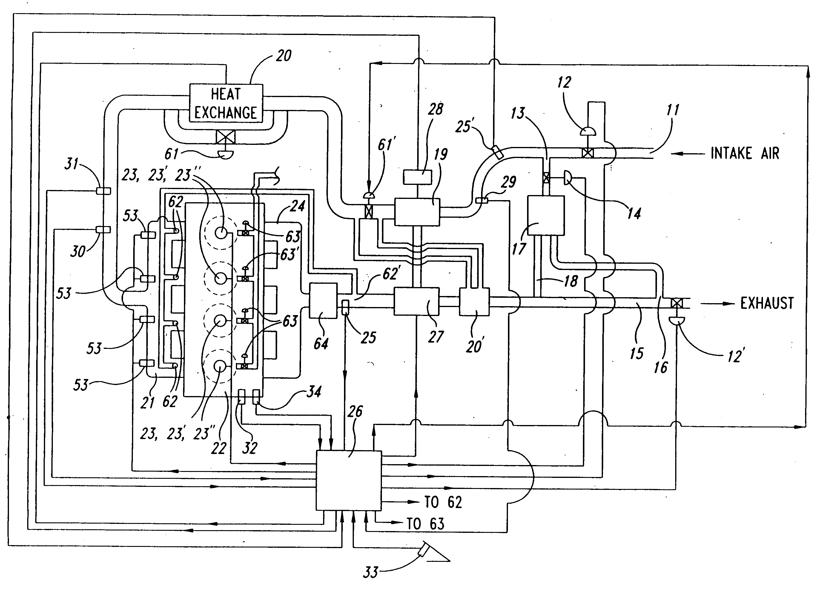
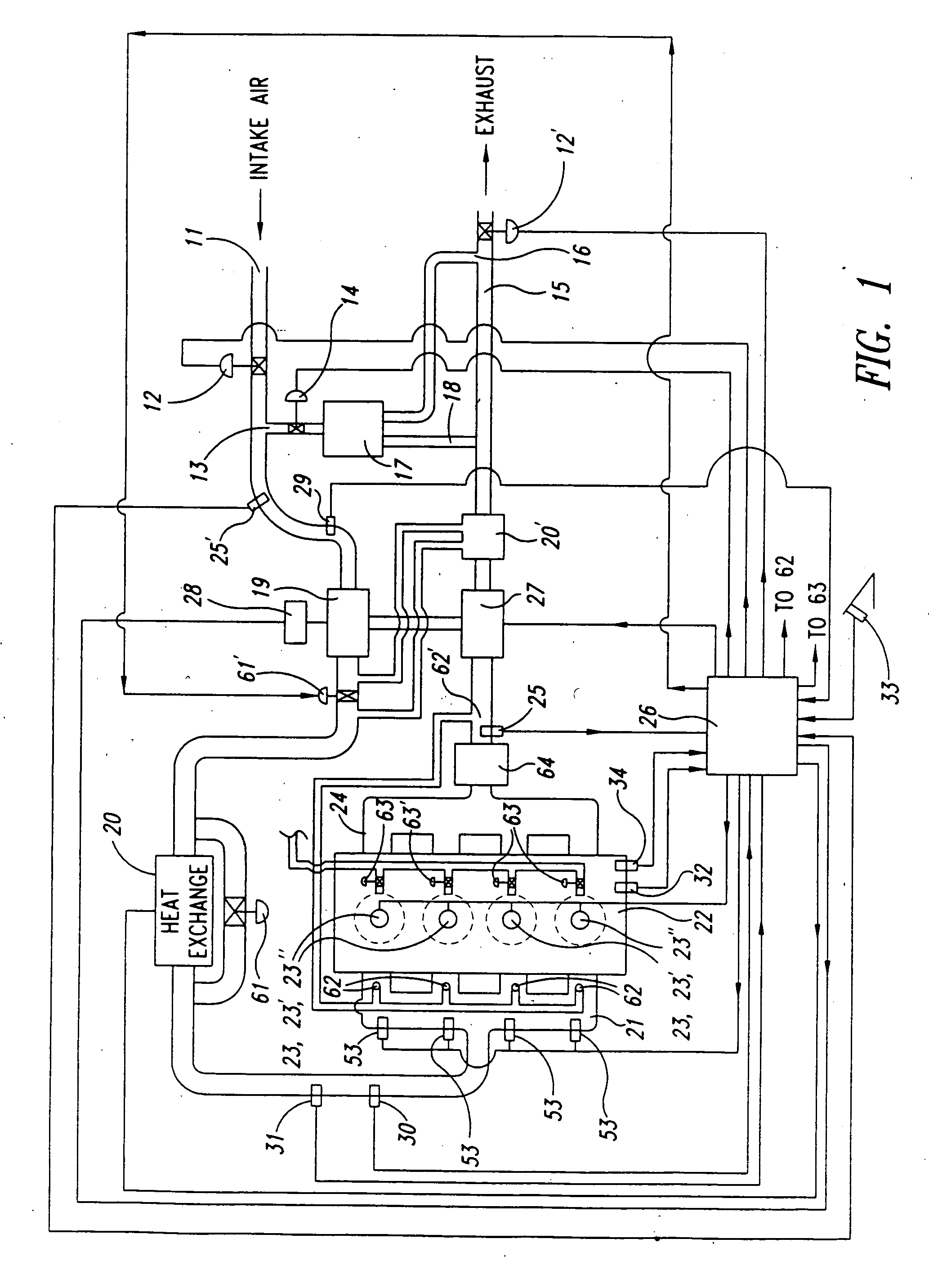
[0034]FIG. 1 shows a preferred embodiment for an HCCI combustion system for multicylinder engine 22 in accordance with the present invention. Intake air enters the intake system at port 11 and flows through optional valve 12. Exhaust gas may be mixed with the intake air (forming the charge-air2 mixture) at port 13, with EGR control valve 12′ in the exhaust line 15 creating an exhaust back pressure to force exhaust gas to flow through port 16, through optional cooler 17 (with optional condensate return line 18) and through optional on-off control valve 14 to port 13. (An alternate “high pressure” EGR system may instead be used which would connect the exhaust line before turbine / motor 27 with the intake line after compressor 19.) The charge-air then flows through optional compressor 19, which may be driven by turbine / motor 27 and / or optional motor 28. The compressor 19 and motors 27 and 28 may be single units or multiple units in series or parallel, as will be known in the art.

2The t...


PUM


Abstract

The present invention provides a multicylinder homogeneous charge, compression ignition (HCCI) type engine, also known as a premixed charge compression ignition (PCCI) engine, with a control system designed to maintain stable, efficient, low emission HCCI combustion during engine transitions from one speed/load operating point to another speed/load operating point. HCCI combustion control in the invention is obtained by adjusting specified “engine operating parameters” that influence the crank angle location of the combustion event (viz., charge-air intake temperature, intake pressure (boost), charge-air oxygen concentration, engine cooling, and engine compression ratio), in coordination with adjustments in fuel quantity, by the following preferred method: (1) determining an existing “combustion parameter” value such as the maximum rate of pressure rise (MRPR), for each cycle of each cylinder, (2) adjusting an engine operating parameter of the engine to effect a change in said combustion parameter value, (3) thereafter adjusting an engine “control parameter” (e.g., commanded fuel quantity) to each cylinder, responsive to the effect of the adjusted engine operating condition, to maintain a desired target for the combustion parameter value, and (4) individually adjusting cooling, heating and/or fuel command to individual “outlier” (deviating) cylinders, to achieve uniform combustion. Preferred control strategies to maximize HCCI combustion stability are also set forth, such as averaging sensed combustion parameter values and/or ignoring combustion-parameter values within a specified dead band region so as to ignore cycle-to-cycle random variations of the combustion parameter values at stable HCCI operating points. Additional methods to minimize such engine combustion variability include increasing intake pressure (boost) and controlling combustion chamber cooling, and are additionally described.

Description

CROSS REFERENCE TO RELATED APPLICATIONS [0001] This application is a continuation-in-part of U.S. application Ser. No. 10 / 665,634, now pending, which incorporates by reference and is a continuation-in-part of U.S. Pat. No. 6,651,432, “Controlled Temperature Combustion Engine,” filed Aug. 8, 2002, both of which applications are incorporated herein by reference in their entirety.BACKGROUND OF THE INVENTION AND DESCRIPTION OF RELATED ART [0002] The present invention relates to methods for controlling combustion in a multicylinder controlled temperature combustion engine using gasoline-like fuel, particularly in a homogeneous charge, compression ignition (HCCI) type engine, also known as a premixed charge compression ignition (PCCI) engine. [0003] Various prior art publications recognize that several parameters influence the initiation of combustion in an HCCI engine. See, for example, U.S. Pat. No. 6,286,482 to Flynn, et al., and Aceves, HCCI Combustion: Analysis and Experiments, SAE 2...

Claims


Application Information

Patent Timeline
IPC IPC(8): F02B1/12F02B5/00F02B29/04F02D35/02F02D41/00F02D41/30F02D41/34F02M25/07G06F17/00
CPCF02B1/12F02B29/0493F02D35/023F02D41/008F02D41/3035Y02T10/146F02D2200/0414F02M25/0709F02M25/0728F02M25/0754Y02T10/128F02D2200/0406F02M26/06F02M26/25F02M26/47Y02T10/12F02B5/00F02D35/02F02D41/30G06F17/00
Inventor GRAY, CHARLES L. JR.
Owner ENVIRONMENTAL PROTECTION AGENCY US
Why Eureka
Try Eureka