Real-time processor system and control method

a real-time processor and control method technology, applied in the field of real-time processor systems, can solve the problems of affecting the processing of the generated later, affecting the processing efficiency of the interrupt controller, and affecting the execution of the program for changing the i/o access priority,

Inactive Publication Date: 2005-03-24
PANASONIC CORP
View PDF15 Cites 16 Cited by
  • Summary
  • Abstract
  • Description
  • Claims
  • Application Information

AI Technical Summary

Benefits of technology

[0016] An object of the present invention is to provide a real-time processing and a control method thereof operable to providing every bus master with individual interruption processing means, and operable to adaptively control bus arbitration priority for both of multiple interruption and processing other than interruption processing, in the environment where a plurality of bus masters arbitrate and uses a bus.

Problems solved by technology

However, when program execution itself needs the I / O access, for example, when the program itself is stored in a memory that is one of the shared I / O devices, there is a striking delay in the program execution for changing the I / O access priority, since the I / O access is required for the program execution of interruption processing.
Therefore, when another interruption occurs during the interruption processing generated previously (in a case of multiple interruption), the interruption processing generated later is performed with lower I / O access priority until the interruption processing generated previously is completed, thus delaying the processing generated later drastically.
Therefore, an interruption controller cannot be arranged individually for every processor.

Method used


Image

  • Real-time processor system and control method
  • Real-time processor system and control method
  • Real-time processor system and control method

Examples


first embodiment

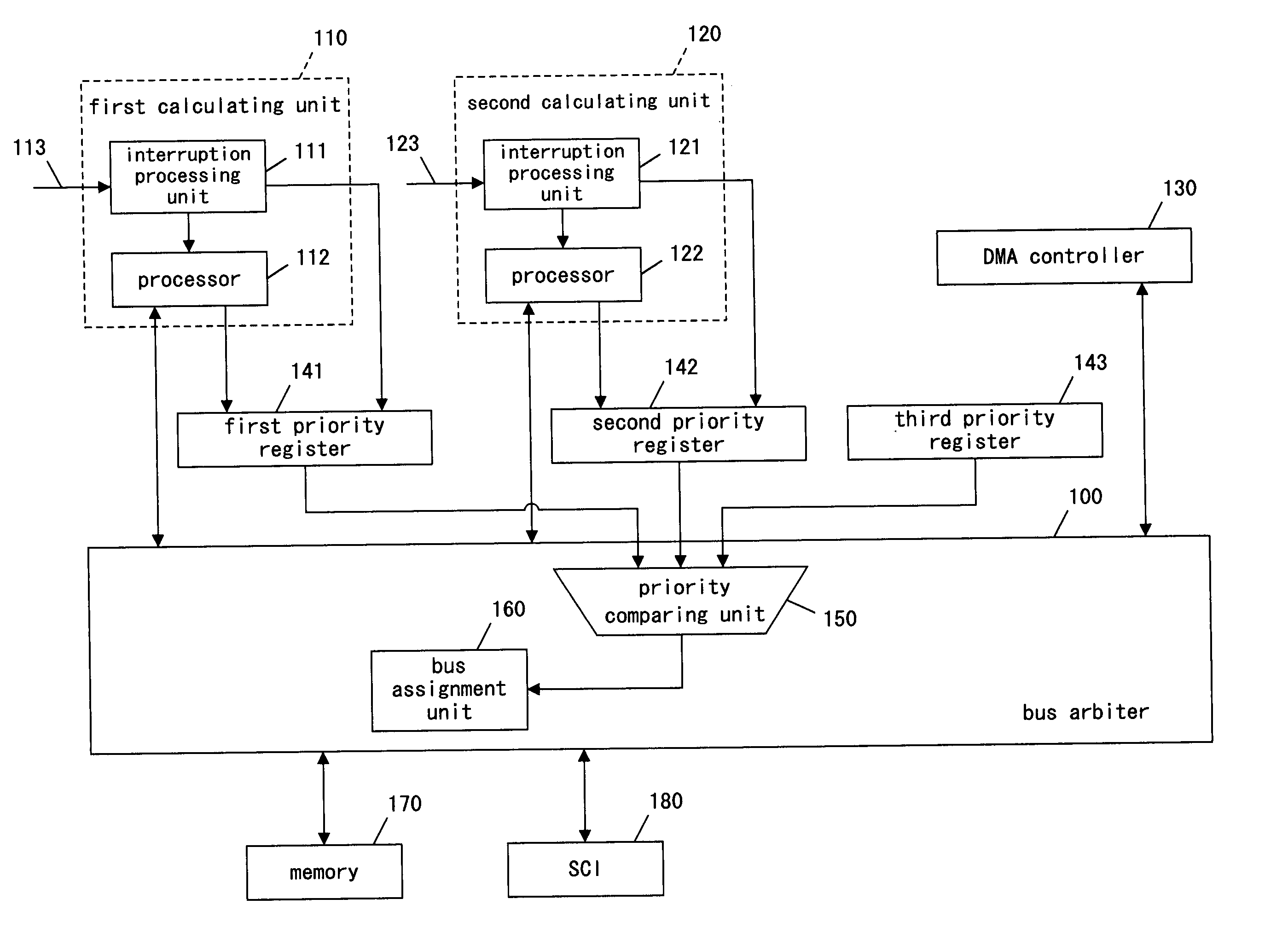
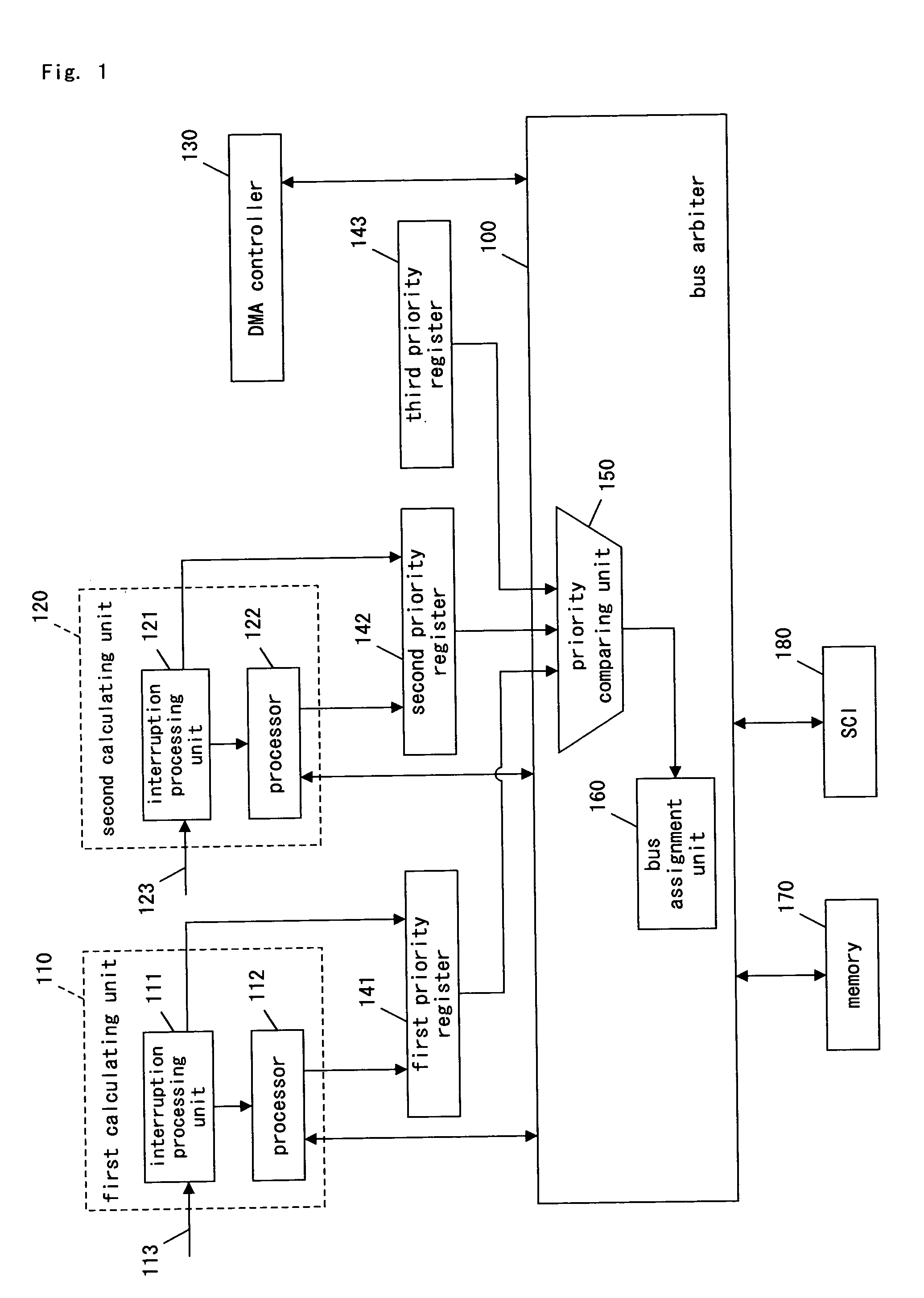
[0055]FIG. 1 is a block diagram of a real-time processor system in a first embodiment of the present invention.

[0056] The real-time processor system of the present embodiment comprises a bus arbiter 100, a first calculating unit 110, a second calculating unit 120, a DMA controller 130, a first priority register 141, a second priority register 142, a third priority register 143, a memory 170, and an SCI (Serial Communication Interface) 180.

[0057] The first calculating unit 110 includes an interruption processing unit 111 and a processor 112, the second calculating unit 120 includes an interruption processing unit 121 and a processor 122, and the bus arbiter 100 includes a priority comparing unit 150 and a bus assignment unit 160. The first priority register 141 stores the I / O access priority value of the first calculating unit 110, and the second priority register 142 stores the I / O access priority value of the second calculating unit 120. The third priority register 143 stores a f...

second embodiment

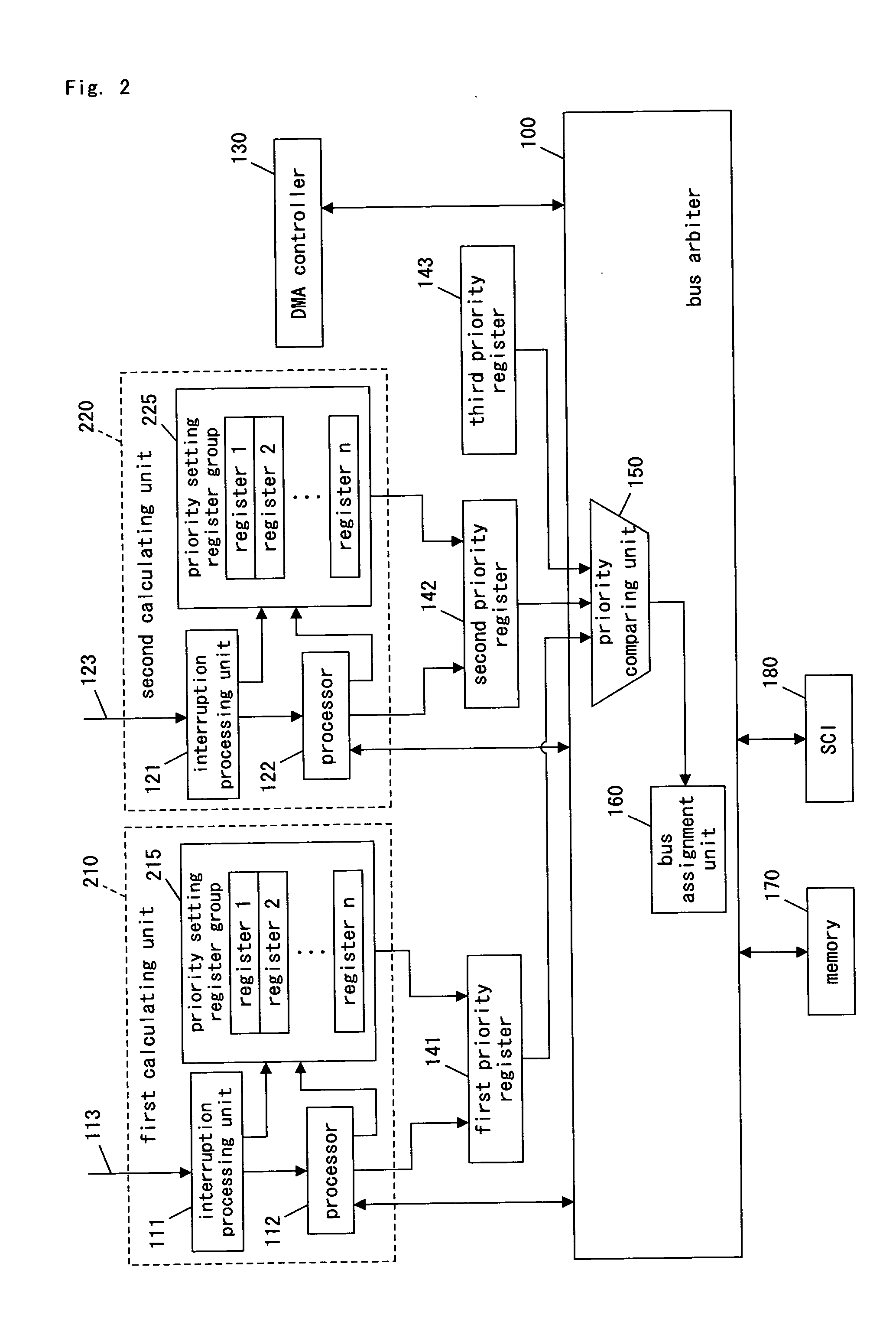
[0083]FIG. 2 is a block diagram of a real-time processor system in a second embodiment of the present invention. In FIG. 2, descriptions are omitted by giving the same symbols regarding the same components as in FIG. 1.

[0084] The real-time processor system of the present embodiment shown in FIG. 2 comprises the bus arbiter 100, a first calculating unit 210, a second calculating unit 220, the DMA controller 130, the first priority register 141, the second priority register 142, the third priority register 143, the memory 170, and the SCI 180. The first calculating unit 210 includes the interruption processing unit 111, the processor 112, and a priority setting register group 215. The second calculating unit 220 includes the interruption processing unit 121, the processor 122, and a priority setting register group 225.

[0085] The first calculating unit 210 and the first priority register 141 belong to a first function group and the second calculating unit 220 and the second priority ...

third embodiment

[0102]FIG. 3 is a block diagram of a real-time processor system in a third embodiment of the present invention. In FIG. 3, descriptions are omitted by giving the same symbols regarding the same components as in FIG. 1.

[0103] The real-time processor system of the present embodiment shown in FIG. 3 comprises the bus arbiter 100, the first calculating unit 110, the second calculating unit 120, the DMA controller 130, a first priority register 341, a first comparator 345, a second priority register 342, a second comparator 346, the third priority register 143, the memory 170, and the SCI 180.

[0104] The bus arbiter 100 includes the priority comparing unit 150 and the bus assignment unit 160.

[0105] The first calculating unit 110, the first priority register 341, and the first comparator 345 belong to a first function group. The second calculating unit 120, the second priority register 342, and the second comparator 346 belong to a second function group. The third priority register 143 ...


PUM


Abstract

A real time processor system comprises: a bus arbiter; a plurality of calculating units, each having a processor and an interruption processing unit; a DMA controller; a plurality of priority registers; a memory; and an SCI. The bus arbiter comprises: a priority comparing unit; and a bus assignment unit. Each of the plurality of priority registers stores an I/O access priority value corresponding to each of the calculating units. Priority values are compared, and then right of I/O use is determined. The values of the plurality of priority registers are changed, thereby adaptively performing multiple interruption processing.

Description

BACKGROUND OF THE INVENTION [0001] 1. Field of the Invention [0002] The present invention relates to a real-time processor system and a control method thereof in environment where a plurality of bus masters arbitrate and use a bus. [0003] 2. Description of the Related Art [0004] Conventionally, in providing real-time guarantee for software in environment where there is only one processor as a device that works as a bus master, the real-time guarantee is afforded by assigning priority per unit of processing and appropriately scheduling starting order for the processing. [0005] For example, reference 1 (“HARD REAL-TIME COMPUTING SYSTEM, Predictable Scheduling Algorithms and Applications”, written by Giorgio C. Buttazzo, Fourth Printing 2002, Kluwer Academic Publishers, pp.109-146 and pp.149-178) discloses, in pages 109-146, that when fixed priority is given for each processing, a method that assigns higher priority to processing with shorter executing time is best suited in minimizing...

Claims


Application Information

Patent Timeline
Patent Type & Authority Applications(United States)
IPC IPC(8): G06F13/362G06F9/46G06F13/00G06F13/14G06F13/24G06F13/26G06F15/16
CPCG06F13/362G06F13/26G06F9/46G06F13/14G06F15/16
Inventor FUCHIKAMI, RYUJIYONEZAWA, TOMONORINISHIDA, YOICHI
Owner PANASONIC CORP
Why Eureka
Try Eureka