Combined torque measurement and clutch apparatus

a technology of torque measurement and clutch apparatus, which is applied in the direction of instrumentation, structural/machine measurement, machine part testing, etc., can solve the problems of inaccuracy of torque measurement, and achieve the effect of wide application potential and more measurement accuracy

Inactive Publication Date: 2005-03-31
PRATT & WHITNEY CANADA CORP
View PDF5 Cites 1 Cited by
  • Summary
  • Abstract
  • Description
  • Claims
  • Application Information

AI Technical Summary

Benefits of technology

[0017] The apparatus according to the present invention combines a clutch device with a torque measurement device and can have broad application potential, because of not only providing a new option for machine structure design, but also providing a new torque measurement method which provides more measurement accuracy. The latter is advantageous, particularly at low torque levels compared to a full load torque level of the machine into which the apparatus is incorporated.

Problems solved by technology

Nevertheless, the rotating shaft is generally designed for full load torque transmission and therefore the angular deviation of the rotating shaft at a low torque level will be relatively small, resulting in inaccuracies in the torque measurement.

Method used


Image

  • Combined torque measurement and clutch apparatus
  • Combined torque measurement and clutch apparatus
  • Combined torque measurement and clutch apparatus

Examples


Embodiment Construction

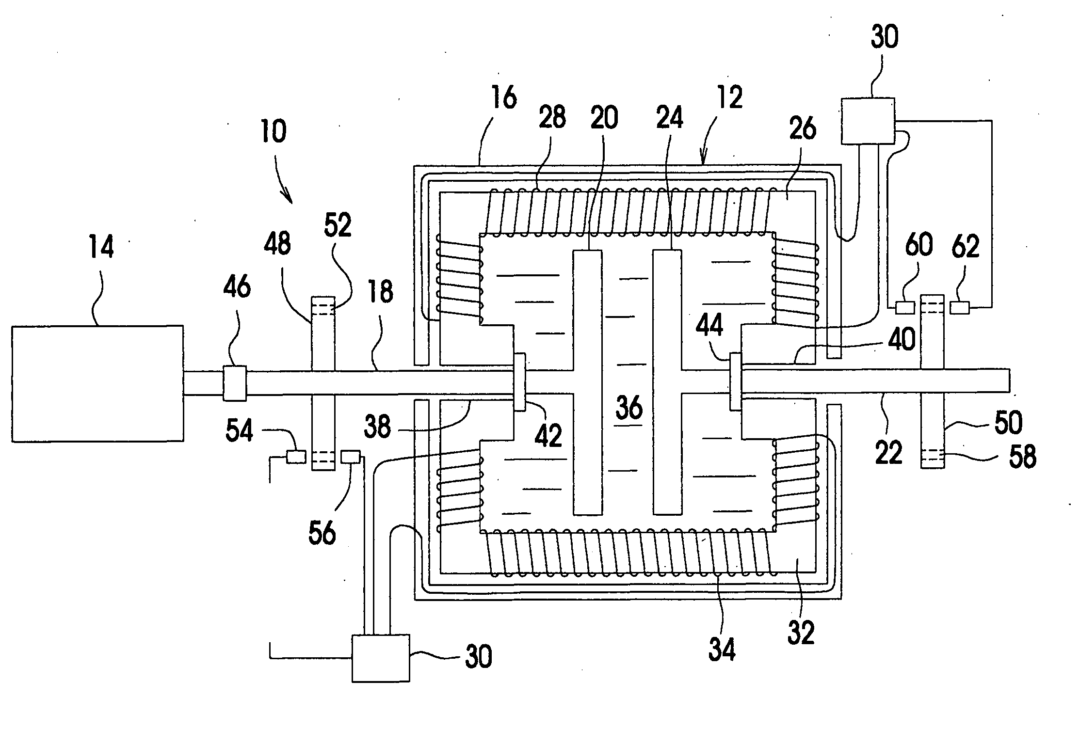
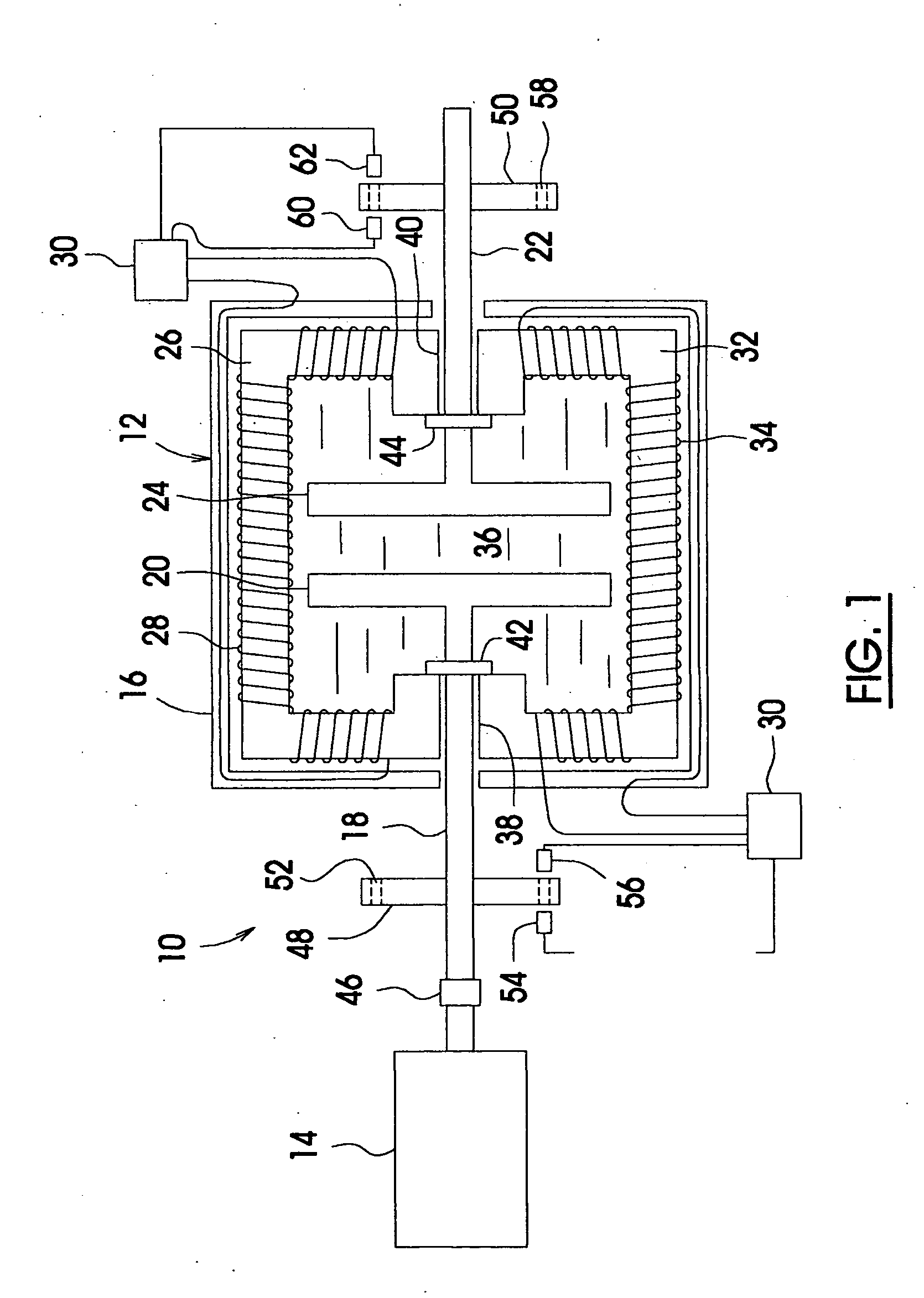
[0022] With reference to FIG. 1, an apparatus of the present invention generally designated at numeral 10, includes a magnetic fluid clutch 12 which is directly coupled to an engine 14, and thereby forms a torque output end of the engine 14. The magnetic fluid clutch 12 includes a casing 16 supported on a stationary structure (not shown) of the engine 14. A torque input shaft 18 extends outwardly from the inside of the casing 16 and is rotatable relative to the casing 16. A first plate 20 is attached to the inner end of the torque input shaft 18 and is rotatable together with the shaft 18. The magnetic fluid clutch 12 further includes a torque output shaft 22 which extends, oppositely with respect to the torque input shaft 18, outwardly from the inside of the casing 12 and is rotatable relative to the casing 12. A second plate 24 is attached to the inner end of the torque output shaft 22 and is rotatable together with the shaft 22. The torque input and output shafts 18, 22 are posit...


PUM

PropertyMeasurementUnit
torqueaaaaaaaaaa
phase shift measurementaaaaaaaaaa
magnetic fieldaaaaaaaaaa

Abstract

A method of using a magnetic fluid clutch for torque measurement comprises steps of modulating electric current through a coil of the magnetic fluid clutch to maintain a steady-state quasi-solid phase of a magnetic fluid medium contained within the magnetic fluid clutch when the magnetic fluid clutch is clutched to transmit torque from a torque input end of the clutch to a torque output end of the clutch, thereby ensuring that the torque output end rotates in response to the rotation of the torque input end without relative rotational slippage therebetween; and measuring a deflection value associated with the magnetic fluid clutch. The clutch is thereby used as a combined torque measurement and clutch apparatus.

Description

FIELD OF THE INVENTION [0001] The present invention generally relates to torque measurement, and more particularly to a method of using a magnetic fluid clutch for torque measurement as well as to a combined torque measurement and clutch apparatus for use with this method. BACKGROUND OF THE INVENTION [0002] Engines which are utilized in single-engine helicopter applications typically incorporate a freewheeling clutch and a separate torque measuring device which is within or attached to the reduction gear box, or is attached to a drive system of the helicopter in order to establish torque transmission to the main rotor and to monitor the torque value transmitted to the main rotor, or facilitate auto-rotation in the event of a reduction or loss of engine power. [0003] It is known that torque measurement can be achieved by a phase shift measuring device used to measure an angular deviation between two ends of a rotating shaft which transmits torque. One example of such a phase shift me...

Claims


Application Information

Patent Timeline
Patent Type & Authority Applications(United States)
IPC IPC(8): F16D37/02G01L3/14
CPCF16D37/02G01L3/1492F16D2037/002
Inventor ANDERSON, STEPHEN ARTHUR
Owner PRATT & WHITNEY CANADA CORP
Why Eureka
Try Eureka