Continuous fluid sampler and method

a fluid sampler and continuous technology, applied in the field of sampling arrangement, can solve the problems of system degradation or contamination of the system being sampled, system design or retrofitting, and the inability to meet the requirements of the system, etc., to achieve simple and inexpensive retrofitting, easy and inexpensive, and convenient and inexpensive effect of achieving system maintenance and repair

Inactive Publication Date: 2005-03-31
QUALITY MANAGEMENT
View PDF14 Cites 13 Cited by
  • Summary
  • Abstract
  • Description
  • Claims
  • Application Information

AI Technical Summary

Benefits of technology

[0010] The present invention provides an efficient, effective and reliable assembly and method for aseptic continuous sampling of a fluid material. The principles of this invention can be simply implemented with readily available materials and techniques that enable application of the invention to sampling equipment of original design, as well as to relatively simple and inexpensive retrofitting of existing fluid enclosures or fluid transportation systems. The principles of this invention can readily be implemented in kit form for retrofitting applications. Further, replacement of expendable parts for maintaining the sampling system can be readily and inexpensively achieved without costly system down time and by minimizing contamination to the sampled system.

Problems solved by technology

Such systems typically require redesign or retrofitting to accommodate sampling functions.
Such retrofitting can be expensive and / or difficult to achieve, can require significant system downtime in implementation of the sampling function and / or replacement of parts to maintain the system, or can lead to system degradation or contamination of the system being sampled.
Problems arises from this method as this method is not aseptic because the gasket becomes so perforated after repeated sampling that the gasket may lose its sealing integrity or introduce contaminants into the system though the perforations.
This method requires that the gasket be replaced, which can become expensive both in labor costs and shut down costs.
While continuous sampling techniques have been tried, they have generally not been particularly effective, efficient or reliable in maintaining the aseptic condition of the system during the sampling interval.
Known discrete sampling techniques have not proven to be readily adaptable to continuous sampling techniques.
For example, if the sample is taken from a region of laminar fluid flow, the sampling needle can create a venturi effect in the fluid flow being sampled, which can cause reverse flow siphoning from the collected sample and back into the sampled fluid.
If such suction effect is disrupted by providing the sampling system with an air gap, the aseptic nature of the sampling system is compromised.

Method used


Image

  • Continuous fluid sampler and method
  • Continuous fluid sampler and method
  • Continuous fluid sampler and method

Examples


Embodiment Construction

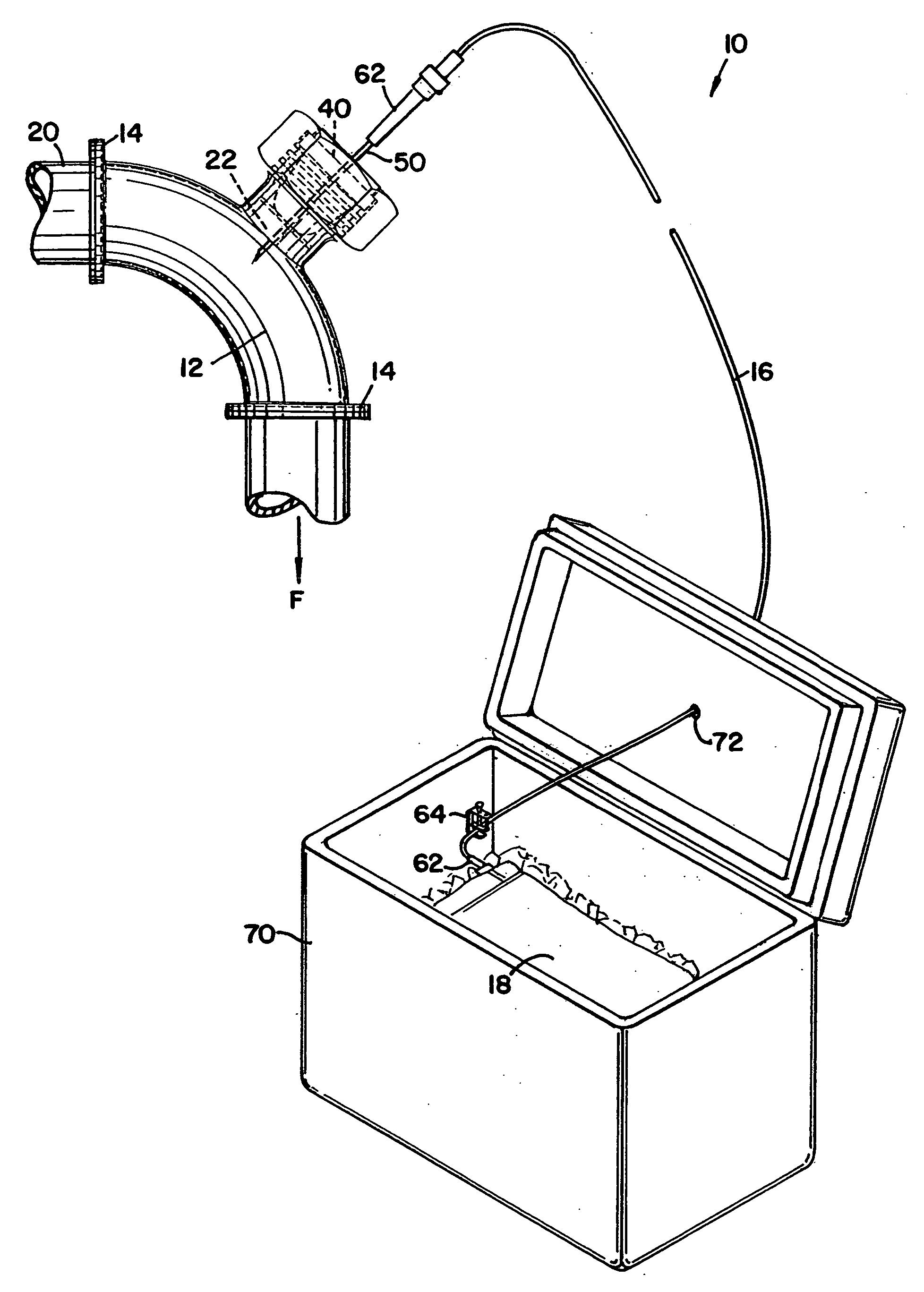
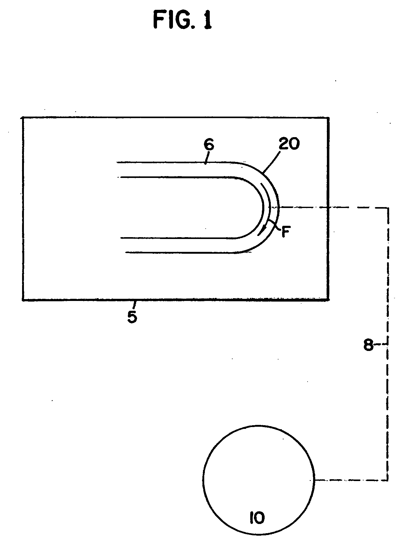
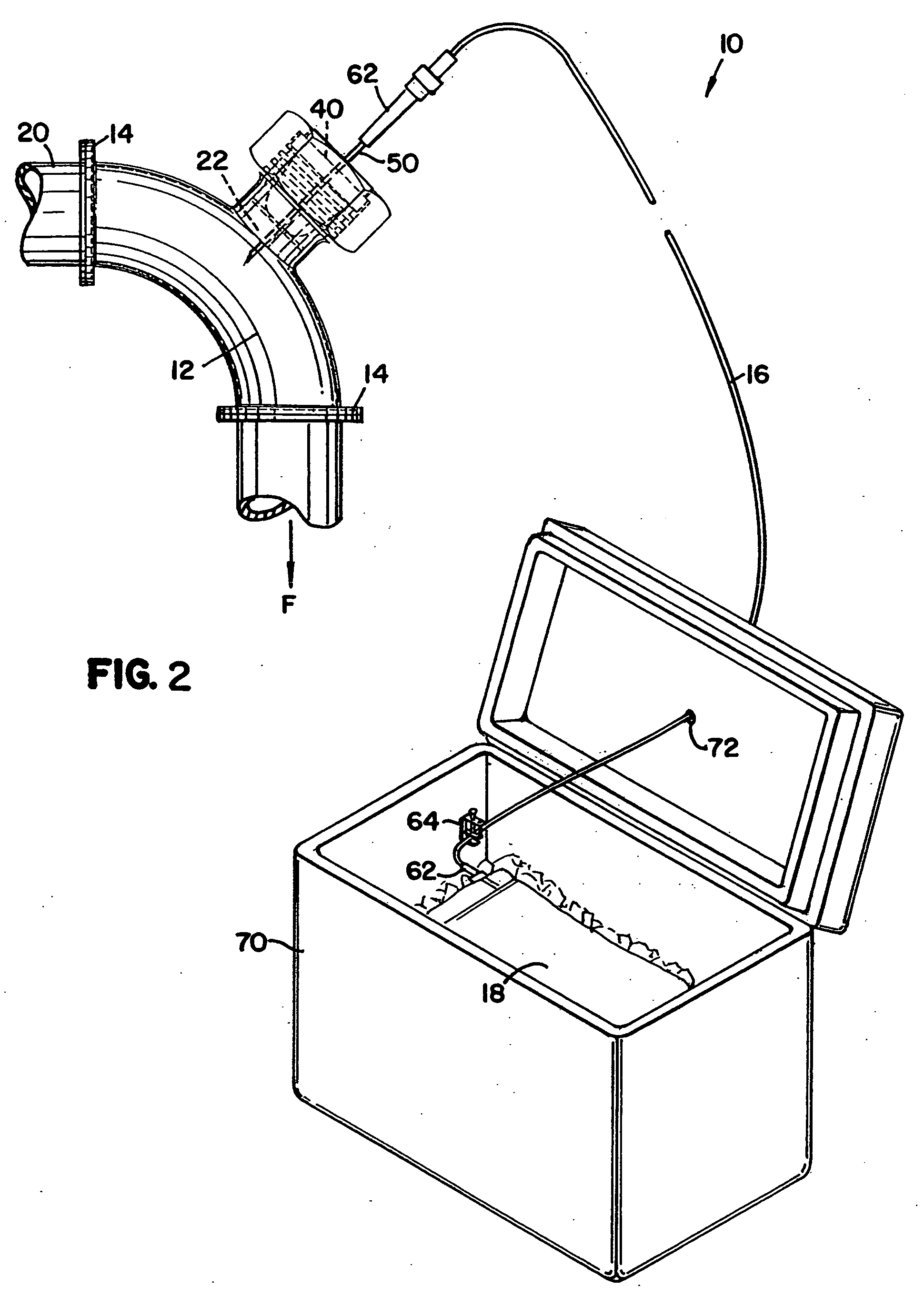
[0025] This invention provides an apparatus and method for the continuous aseptic sampling of fluid material from a fluid transportation system or fluid processing enclosure 5, schematically illustrated in FIG. 1. A fluid material 6 to be sampled is illustrated as flowing through a fluid line 20 by the fluid flow arrow designation “F”. A preferred sampling arrangement of the present invention is schematically illustrated at 10 and is depicted as operatively connected, by the dashed line 8, to sample the fluid material 6 (as hereinafter described in more detail).

[0026] The principles described herein for the sampling arrangement 10 can be used in various industries and in various applications where aseptic sampling of material is desired. Aseptic sampling involves transferring fluids to or from process systems that are sensitive to contamination from the outside environment. For example, the pharmaceutical, bioengineering / biotechnology, brewing / distilling, food processing and dairy ...


PUM

PropertyMeasurementUnit
diameteraaaaaaaaaa
diameteraaaaaaaaaa
lengthaaaaaaaaaa

Abstract

An aseptic, continuous sampling arrangement used in a fluid transportation system, the arrangement including an elbow pipe and a septum cartridge. The sampling arrangement further including a needle, a tube, and a collection reservoir, arranged such that the collection reservoir is in fluid contact with the fluid transportation system. The sampling arrangement configured to create a non-laminar fluid flow region from which a continuous sample of fluid material is drawn.

Description

CROSS-REFERENCE TO RELATED APPLICATIONS [0001] This application is a divisional of application Ser. No. 10 / 022,294, filed Dec. 14, 2001; which application is incorporated herein by reference.FIELD OF THE INVENTION [0002] This disclosure concerns a sampling arrangement. More specifically, this disclosure describes the assembly and method of use of a sampling arrangement for aseptic, continuous sampling of a fluid material. BACKGROUND OF THE INVENTION [0003] There are numerous applications wherein it is desirable to obtain discrete or continuous samples from fluid transportation systems or fluid processing enclosures. Enclosures and fluid transportation systems, as used herein, refer to any closed containment structure without respect to its size. Thus it includes such small enclosures such as cans that may be used in shipping starter bacteria from a culture lab. On the other end of the spectrum, it includes large tanks and associated pipelines, which may have capacities of several th...

Claims


Application Information

Patent Timeline
Patent Type & Authority Applications(United States)
IPC IPC(8): G01N1/00G01N1/10G01N1/20
CPCG01N1/2035G01N2001/1093G01N2001/1056G01N35/1079
Inventor BIGALKE, DARRELL LEE
Owner QUALITY MANAGEMENT
Why Eureka
Try Eureka